This thread has been locked.

If you have a related question, please click the "Ask a related question" button in the top right corner. The newly created question will be automatically linked to this question.

LMR50410-Q1: Only one pulse of power comes out at light load

Part Number: LMR50410-Q1

Hi Team,

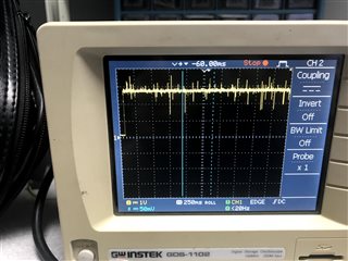
Our customer is using LMR50410Y5FQDBVRQ1 for their project. However, when the customer connected an LED with series resistor, only one pulse comes out of the regulator. She added a microcontroller to increase the load but the result is the same, the regulator output once and then it turned off. She started from 4V and increased the voltage. The 5V pulse output just became quicker as the voltage went up.

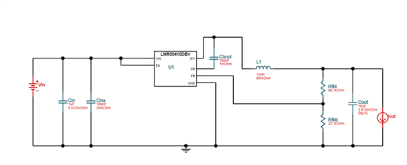
She added some RGB LED with resistors and it worked for higher voltages. When she switched the 15uH inductor for a 18 uH inductor, the output works with 4V and 12V but not for 5-5.5V. For the customer's application, the regulator will supply power to a microcontroller, typically 8-10mA and biggest load would be at 230mA. What could be the cause of the regulator not generating output voltage at 5-5.5V? Below is the schematic diagram from the customer.

Regards,

Danilo

  • Danilo,

    Please share scope shots of what you're describing. Also share the layout.

    Schematic:

    • CIN should be at least 2.2uF (50V X7R) + 100nF
    • CBOOT should be rated to 16V or higher

    I'm not sure I understand fully. Are you saying:

    • The regulator is regulating to 4VOUT with no load, then you connect an LED (with load resistor) and see one pulse on SW, then the output falls to 0V? I think some scope shots should help clear this up.

    -Sam

  • Hello, 

    I bought only parts that were in the ranges suggested by the power designer. I tried the exact schematic first before changing part values. I don't have pictures of the scope. Friday evening the regulator quit giving me any output. So I have another one ready now and am about to try it. If it behaves the same I will send scope shots

    The regulator was giving me the rising edge of a square wave at 5v peak, then would discharge back to Zero. The higher the Vin the slower it would discharge. 

  • I am the costumer with the issue

  • Rachel,

    Thanks, please send scope shots if you can. From what I read, here's what I understand:

    • Board built with recommended values - no issues.
    • Values changed, Friday tests showed issue.
    • The issue is that the output quickly rises, then immediately starts discharging like an exponential decay. Higher VIN results in slower discharge.

    Good information would be:

    • Does VOUT stay low or does it keep trying?
    • How long does VOUT stay high before decaying? What's the switch node doing?

    -Sam

  • I am working with the scope now, this new regulator that I am using now is also not working properly but in a different way. I will share pictures in a minute. 

    Vout stays low after discharge. Vout stays at peak value 5v for only a quick second then starts decaying. 

    Now this reg. is outputting a 2.6v no square wave. 

  • Rachel,

    It looks like your ICs are getting damaged somehow. Are any pins exceeding absolute maximum ratings from the datasheet?

    Can you please send your schematic and layout.

    For reference, proper operation should have:

    • VIN > 4V
    • VOUT = 5V (from your schematic feedback divider)
    • SW is switching if in FPWM or pulsing if in PFM (depending on part number trim)
    • FB = 1V
    • CB = 3 to 5V higher than SW at all times

    If FB = 1V and VOUT is not what you expect, there might be something wrong with the resistor divider. If CB-SW voltage is not between 3 and 5V, that capacitor may not have adequate capacitance. There are lots of things that can go wrong and comparing your board to the expected values can give us a clue as to what is going wrong. If none of the above parameters are correct, the device is probably broken but I will need to hear back from you about the above points before we draw conclusions.

    -Sam

  • My schematic is the one posted in the question, I start by putting 4v on the circuit then step it up. I haven't gone over 15 v yet. My load is well below 1 A.  I will check the values on each pin. 

  • Checking the absolute ratings from the data sheet:

    Fb = .625v

    sw = 2.6 v

    cb to sw = 5.24v

  • Rachel,

    Please share the layout.

    If the device was working with recommended values, then not working with new values, please share both schematics so we can compare. And also let me know if the layout changed as well.

    -Sam

  • The device is has not yet worked correctly once. I am using the same schematic. I am not exactly sure by what you mean by "layout" 

    Here is a list of components that I bought for this. Also I have included the suggested ranges. However I am currently using the same ones as the schematic shared in the question.  

    Cin:

    1uF – 10uf    esr:1u-20m ohms               irms 322.4m – 10kA          VDC 45.5 – 105v

    1uf: FG28X5R1H105KRT00

    2.2uf: FG24X7R1H225KRT06

    4.7uF: FG24X5R1H475KRT06

    10uF: FG20X7S1H106KRT06


    L1

    L: 14.44u-20.86u               DCR: 10m-250m ohms                 IDC 1.7A-5.1A

    15u: RLB0912-150KL

    18u: RLB0914-180KL


    Cboot

    C: 0.1uF Vdc: 16v-25v

    FA18X8R1E104KNU00


    Cinx

    C: 0.1uf         ESR 1u-20m ohms  irms 20.52mA- 50A           Vdc: 45.5 – 105v

    K104K15X7RH53H5G


    Cout

    C: 16.11uF – 32.22uF        ESR: 1u – 342.9m ohms    Irms 174.83m – 50A VDC: 7.14-71.43V

    15uF: FG24X5R1E156MRT00

    22uf: RDEC71H226MWK1H03B

    47uf: FG26X5R1E476MRT06

    33uf: FG26X5R1E336MRT00

    Rfbb:

    R: 22.1 kohms                     50-75v                       .1 power rating


    YR1B22K1CC

    Rfbt:

    R: 88.7k ohms         50/75V


    YR1B88K7CC

  • Also, it wasn't clear in this above post but these are what I got for my pin values. 

  • I am not using a PCB

  • I tried a 3rd reg. (of the same) and that one is also acting differently. I am getting a different output based on input. I am getting a closer output with no load, but with a load it drops. 

  • Rachel,

    1. Did you check absolute maximum values during startup and worst case or only during the condition with the issue? We will need to check abs max before the issue since the issue would happen after violating abs max.

    2. "I am not using a PCB" - How are you testing this? Is it on the evaluation board or on a custom board?

    3. Do you have a schematic to share? I gave comments on the original schematic, and the values you gave are ambiguous. Are all of those components on the board? Are some of those components on the board? Which ones? A schematic would clarify and make sure we're on the same page.

    4. The layout is the document showing how/where the components are placed and how they are connected with copper. Please share this or share pictures of this so I can see if the components are placed appropriately.

    -Sam

  • Rachel,

    I have not heard back so I will close this thread. Reply if you still need help.

    Thanks,

    -Sam

  • Close the thread, i was not aware that the device had a to be on a pcb to work