


Other Parts Discussed in Thread: LM5117
Hello,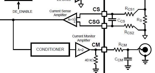
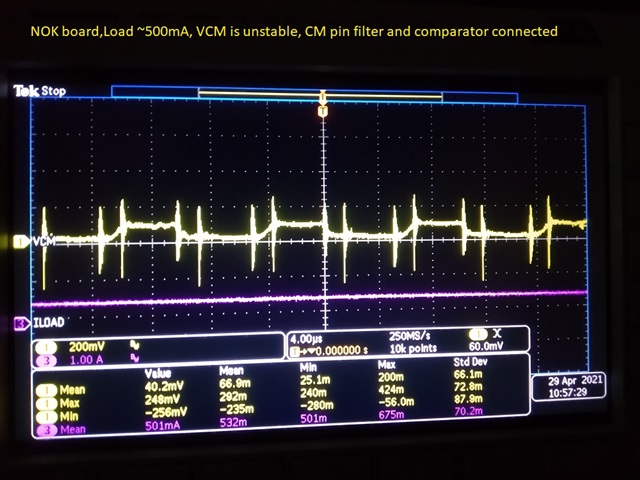
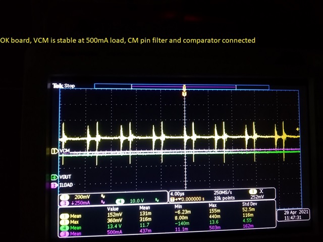
I have one technical query related to LM5117. We are using this PWM controller in one of the 28V to 13,5V/20A DC-DC converter. This is in production. At assembly plant, at EOL station, some of ECUs fail as they do not give regulated output of 13.5V +/-0.5V. We are testing output at 500mA load current at EOL station.
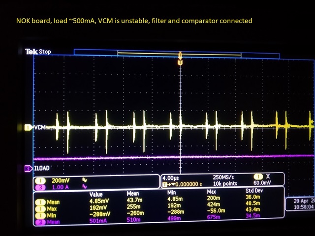
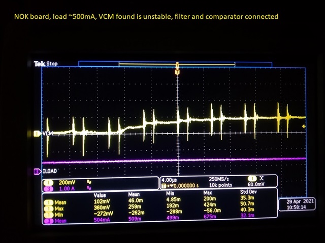
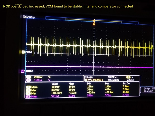
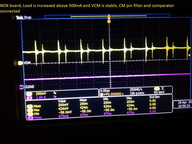
In design, we have implemented a comparator circuit. Current monitor output of PWM controller is given to comparator and it is compared against the reference voltage. Output of comparator controls the UVLO pin of IC. Reference voltage is set such that, comparator output is high for load current > 400mA. But it is observed that UVLO pin is switching continuously between high and low. As a result, output is not regulated.
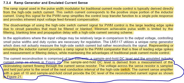
Query regarding this failure is, we are using CM output for comparison. Now at 500mA load current, converter will work in DCM mode and as per datasheet of IC, current sense amplifier samples the voltage across current sense resistor just before turning on high side switch. But when converter is operating in DCM as in our case at 500mA, voltage across current sense will be 0V, before turning on high side switch. So this will result in 0V CM voltage. (We are using diode emulation) and we suspect, that is causing output of comparator to low at 500mA.
Please answer to below queries considering above scenario:
- Is it reliable to consider CM voltage in DCM mode operation?
- What will be CM output voltage in DCM mode?
- Does current sense amplifier sample voltage across current sense resistor just before turning off of LS switch or just before turning on HS switch (As explained earlier, diode emulation mode is used)?
Please let us know your response to above queries asap as this ECU is in production.


 Best Regards