This thread has been locked.

If you have a related question, please click the "Ask a related question" button in the top right corner. The newly created question will be automatically linked to this question.

LM5117: Simulation of external clock synchronization

Part Number: LM5117
Other Parts Discussed in Thread: LM5145, LM5143-Q1

Team,

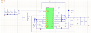
we are trying to simulate the chip LM5117 in LTspice. The main functionalities are working perfectly, like adjusting the output voltage through the Rfb2 resistor.

Now I would like to simulate the external clock synchronization using the pin RT and the circuit in this image:

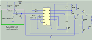
I would like to know if my setup is correct or if I’m doing it wrong.

Thank you and kind regards,

Alen

  • Hi Alen,

    That SYNC IN circuit looks fine.

    Regards,

    Tim

  • Hi Tim,

    thank you for the support! I have another question:

    Please find attached a schematic of my circuit.

    The idea behind this circuit was to make a DC-DC converter that has a Vin of up to 60V and a variable output voltage between ~0V and 48V with a max. current of 20Amps.

    Would you say this scenario is possible to achieve with the LM5117? After doing some experiments at our site, the chip and some other components (M1, L1_1, Cout1) are getting hot.

    Regards,

    Alen

  • Hi Alen,

    You may want to review component selection, especially the MOSFETs and inductor, given the high output current. For example, take a look at the LM5145 5V/20A/225kHz EVM that uses 80V FETs.

    The thermal performance is also dictated by the max ambient temperature. A two-phase solution with the LM5143-Q1 is another option.

    Regards,

    Tim