This thread has been locked.

If you have a related question, please click the "Ask a related question" button in the top right corner. The newly created question will be automatically linked to this question.

UCC28950: Short-circuit vs overload behaviour

Part Number: UCC28950
Other Parts Discussed in Thread: UCC27714EVM-551,

Hello,

This thread is a continuation of the following one, as recommended: UCC27714EVM-551: how to test cycle-by-cycle current limit - Power management forum - Power management - TI E2E support forums

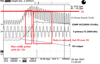
I applied a short circuit at the output of the UCC27714EVM-551, and finally I got a level over 2V in the CS signal.

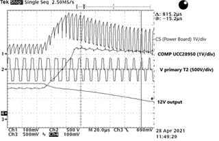
During the first pulses, while the COMP pin is increasing its level up to saturation, there's no cycle-by-cycle current limit, and full-width pulses are applied to the transformer, despite CS being well above 2V. Approximately when the COMP pin saturates, then the pulse-width starts to decrease.

Why there's no cycle-by-cycle current limitation at the start of the short-circuit? Does this mode depend on the COMP in addition to the CS level?

-------------------------------------------------------------------------------------------------------------------

This behaviour seems to be different with an overload (from 50A to 65A approximately) instead of a short-circuit. 

Here it can be seen that even applying a step-load (passive and non-inductive), the primary current is increasing slowly, so there's a current limitation with the COMP not saturated.

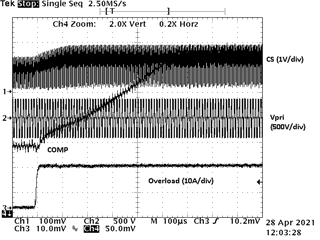
Who is limiting the primary current in the first pulses when the step-load is applied?

This mechanism is limiting the peak current with an overload but not with a short circuit. So the cycle-by-cycle current limit seems to be more complicated than a comparator than compares the (CS+RAMP) with 2V. 

  • The plots that you are showing do not show the CS above 2V.  This would imply the cycle by cycle current limiting is working.  Is there a plot you are not showing?

    Regards,

  • You can see CS above 2V in the first plot.

  • Ch1 is a 100 mV/div and the marking is 200 mV.  Could you double check this please?

  • It's an old oscilloscope and it doesn't recognize the modern probes we are using. The real scale is x10 what the plot says.

    So CH1 and CH4 are 1V/div and CH3 is 5V/div. 

  • Hello,

    The cycle to cycle offset should be controlled to 2V.  It is even tested and has a range of 1.94V to 2.06V.  There is a 100 ns delay that could be causing some of the problem.  However, I noticed in your CS signal it is not returning to ground every switching cycle.

    You might to much filtering on your CS pin.  Please note that if you are using a low pass filter the pole should be at least 10 x above the switching frequency.  You may be creating an offset with leakage spike if there is too much filtering.  I would double check that.  If there is too much filtering reduce it.

    The CS signal should be returning to ground every switching cycle.  The other possibility is that you have offset between the UCC28950 and the scope ground.  Suggested moving scope ground as close to the UCC28950 ground as possible to double check.

    Regards,