This thread has been locked.

If you have a related question, please click the "Ask a related question" button in the top right corner. The newly created question will be automatically linked to this question.

UCC21750QDWEVM-025: Transformer drivers and UVLO test

Part Number: UCC21750QDWEVM-025
Other Parts Discussed in Thread: SN6505B, UCC21750-Q1

Hi E2E,

Good day.

Our customer is using the UCC21750QDWEVM-025 with a power supply of 0-30V DC with 6A rating. When the Vcc voltage is 4.65-.4.75 V, the pull up/down converter is supposed to drive 15 V/-5 V and the supply current is to be a few hundred mAs but they are reading 0.5 V at the secondary output is not 15 V and the supply current is 15mA, neither does the Ready LED turns on. What could be the possible issue, is it with the transformer drivers or the UVLO logic?

They’re able to read the filtered out Vcc(M4) and also the gate driver is not drawing more than 20 mA(M1) @ 4.7 V (M4). Can you suggest methods to test the UVLO or the transformer driver, if this works it will draw 300 mA?

The enable signal to U1 is 3.9 V, they’ve also checked the pin2 and pin 4 for U1 supply it's 5 V. It's supposed to drive the transformer right?,Vdd is still 0 & also the current drawn from supply is 13 mA.

Looking forward to your suggestions.

Regards,
Carlo

  • Please refer to the attached file for some details of the testing conducted.

    TI transformer driver issue.pdf

  • Hi Carlo,

    Welcome to E2E!

    From reviewing the information you sent it seems like a device on the EVM is not working properly, more specifically U1 the SN6505BDBVR driving T1.

    • Does the customer only have one EVM?
      • Easiest way to verify is to test another EVM for comparison.
    • Has there been any modifications to the board?

    Best regards,

    Andy Robles

  • Hello Andy,

    There has been no modification made on the EVM and it was tested as it is. Our customer has ordered the SN6505BDBVR and also another EVM module. I have also requested the result of the testing comparison between the old and new EVM. Once it is available, I will share it with you.

    Regards,
    Carlo

  • Thanks, Carlo. We will await more information.

  • Hi Andy,

    Our customer has tested the new board, apparently, the same issue was experienced.  They have also bought two gate drivers and none of them are working. Please see attached document for their testing result.

    1106.TI transformer driver issue.pdf

    Your assistance is appreciated.


    Regards,
    Carlo

  • Hi Carlo,

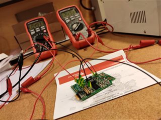
    Would the customer be able to share a picture of how they have the gate driver set up including how it's being probed?

    It's unusual to me that two boards are showing the same behavior and do not output a VDD from only connecting 5V to VCC. I will also be going in to the lab to capture the same measurements the customer has been capturing to verify what the measurements should be on a working board.

    I can get you an update on those lab measurements by Wednesday. Would that be okay for the customers timeline?

    Best regards,

    Andy Robles

  • Carlo,

    Adding to Andy's comments:

    The EN signal to the transformer drivers U1/U5 is set by a window detector and I have personally had issues with it before.

    In the meatime, can you please try the following: Remove U5 IC and replace R26 with 0Ohm or short. EN pin voltage should now match VCC fully, which may solve the issue.

    Best

    Dimitri

  • Hi Andy,

    I have already requested to the customer a picture of their set-up. I will share it with you once available.

    Yes, Wednesday would be okay.

    Hi Dimitri,

    I will let the customer try your suggestion. Thank you.

    Regards,
    Carlo

  • Hi Carlo,

    Thank you let us know if you get any updates. I will update you on the EVM values I capture tomorrow.

    Best regards,

    Andy Robles

  • Hi Andy,

    Here is the set-up of our customer.

    For the PFA connections, they checked the enable signal and it works fine. As of this time, they will try to replace the SN6505B.

    Regards,
    Carlo

  • Hello Carlo,

    Andy is out of the office for the moment, he should respond to you shortly.

    Regards,

  • Hi Carlo,

    I have not been able to go into the lab to check this out, but I do have a couple suggestions. Instead of connecting all the multi meters to the EVM as shown in the user guide could the customer only connect the power supply set to 5V from TP4 to TP6. By simply connecting the power supply from TP4(VCC) to TP6(GND) the EVM should light up both LED's from FLT and RDY circuits, but the customer can also confirm VDD with a multi meter.

    I can't really tell much about the connections on the board from the picture, but my guess is that there may be some disconnections somewhere and it's causing the board to not have VDD.

    Additionally, if the customer has Altium they can download the design files for the EVM from the UCC21750EVM product folder in order for them to see the connections of the board.

    Did they have good results from swapping the SN6505B?

    Best regards,

    Andy Robles

  • Hello Andy,

    According to our customer, their connections are firm and they have also tried with only connecting TP4  and TP6, the Vdd is still 0. They still waiting to receive the SN6505B IC tomorrow, hopefully, that can get the EVM working.


    Regards,
    Carlo

  • Hi, Carlo,

    OK, let us know when they've tested the replacement SN6505B.

  • Hi Andy, Don,

    Our customer had already replaced the transformer driver IC, checked the connections again, it's all working and the IC's receiving the right Vcc(4.9V) & EN (4V) signal. The customer drove few amps with DC supply on the resistor, and it works fine. The primary winding is continuous with 0.4 ohms, the IC is supposed to oscillate but it's unfortunately not the case. It's not working, Vdd is still 0.8 V. 

    Do you have suggestions about their situation?

    Regards,
    Carlo

  • Hey, Carlo,

    I'm not sure I 100% followed you. Here is what I heard. They have measured the voltages on the SN6505B, and both VCC and EN are within spec, yet they don't see any oscillation at pins 1 and 3 which should have a ~425 kHz square wave on it. The customer doesn't see a square wave at those pins?

    I guess for the resistor, you are talking about the primary winding on the transformer?

    Can you ask the customer to use an oscilloscope to probe pins 1 and 3 to see what is going on there? If they don't get the expected 425 kHz signal, ask them to disconnect the transformer to make sure it isn't loading down the SN6505B.

    The customer is applying their 5V supply to TP5 and J2-11, right?  I guess they are if they are measuring 4.9V at the VCC pin of the SN6505B.

  • Hello Don,

    According to our customer, they have tested the old SN6505B as in Fig 36 of SN6505B datasheet which they replaced. It's working fine (5 V, 420 kHz) & it's not faulty as presumed earlier.

    IC oscillation.jfif

    They will take out the transformer T1, to check if they see the same oscillation then it's probably the transformer that is pulling the voltage down.

    The customer has a request if you can check the resistance between Pin1 & 3, of both T1 & T2? Also, the secondary side.

    Thank you.


    Regards,
    Carlo

  • Hi Carlo,

    Would you be able to share who the customer is for this application?

    Are there any other details of this project in which we're trying to win with UCC21750-Q1?

    Best regards,

    Andy Robles

  • Hello Andy,

    The customer is a master's student from KTH and the project is part of a master thesis with BorgWarner & Lund University. 

    They have checked the resistance value and it matches with that of the 750342879-WE T1 datasheet both on the primary & secondary sides. According to the customer during testing, the SN6505B works fine when tested alone but it only oscillates at 1 V when tested between pin 1 & 2 of Transformer T1. They are working on possible issues which can pull the voltage down. Do we have any other suggestions? They are also requesting a sample layout since they don't think the issue is with the transformer.

     IC oscillation_tested alone.jfif

    T1-pin 1 & 2.jfif

    Regards,
    Carlo

  • Hi Carlo,

    If the customer has Altium they can download the design files for the EVM from the UCC21750EVM product folder in order for them to see the connections on the board.

    I've also attached the files on this post: sluraz2(1).zip

    I have also sent you a friend request through this E2E forum with my email. Could you send me an email to continue this conversation over email.

    Best regards,

    Andy Robles