This thread has been locked.

If you have a related question, please click the "Ask a related question" button in the top right corner. The newly created question will be automatically linked to this question.

BQ76920: Can I use 2 of these ICs in parallel with one battery?

Part Number: BQ76920

Hello,

I have been working with the BQ76920 and have very much appreciated all its functionalities. I am designing a BMS for a 12V 100aH battery pack, and I wanted to ask would there be any issues if I use two of these ICs as a means of redundant protection? Each chip will have its own supporting circuitry, the only difference would be that they would control their own set of CHG and DSG Mosfets.

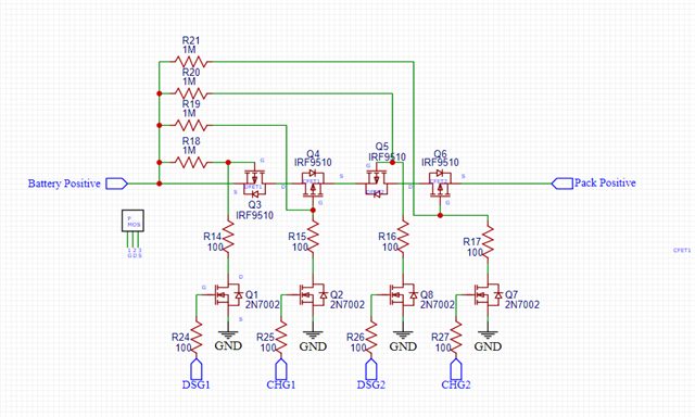
I have modified the circuit to allow for High side driving using p-channel Mosfets, and the Mosfet pairs are put in series so that if a fault is detected from either AFE it will disable the fets.

Here is the circuit for the mosfets:

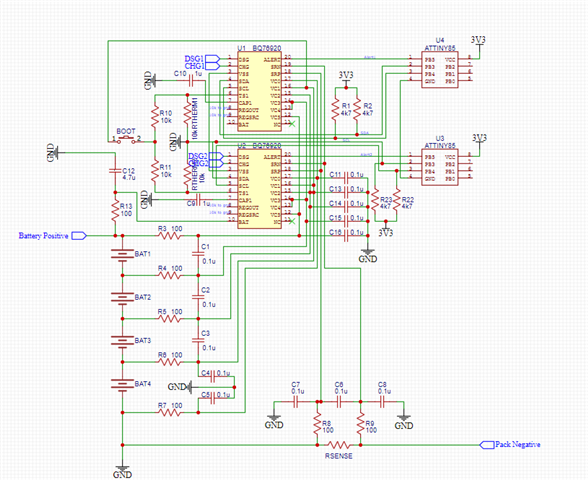
Additionally I have been testing whether each chip needs its own supporting circuitry or if i can use the same components to support both chips. For example, I connected all VC0 to VC5 pins together, and then wired individual cables to the filtered outputs of the cells. 

Here is the circuit, please note not all the connections have been drawn, this is just to let you understand what Im trying to do with the chip. 


So with all that said, Is there any issues with my approach? What would stop one from trying this method of redundant protection rather than looking at secondary protection ICs?

Any guidance here would be much appreciated.

  • Hi Rohaan,

    When monitoring the same battery with 2 different protectors you generally want to keep as much of the protection circuitry separate as possible so that the protection decisions are independent.  So separate filters are recommended.  Sometimes a designer may want separate connectors to the board also but that may be unusual. 

    REGSRC is required and REGOUT needs a capacitor even if you are not using REGOUT for external uses.

    The P-ch switch with redundant FETs should work.  Each FET should have the RGS resistor connected to its source although with a 4S battery the gate voltage may stay in range if pulled up.  The charger may be at a higher voltage than the cells however, so having the charge FETs pulled to PACK+ is likely required. A concern with P-ch switches is the turn off speed particularly of the discharge FETs with a high fault current like a SCD event.  Generally you need a small gate-source resistor to turn off Q3 and Q5 fast enough, the small resistor takes a lot of current from the battery when it is on all the time.  Or you might clamp the gate low when off with some other circuit.  While it is related to a different BMS device and current direction you might see circuit ideas in the application note https://www.ti.com/lit/pdf/slua910 section 3, or drive ideas from www.ti.com/lit/slua618 .