This thread has been locked.

If you have a related question, please click the "Ask a related question" button in the top right corner. The newly created question will be automatically linked to this question.

TPS1HB35-Q1: Circuit diagram review and problem review inquiry

Part Number: TPS1HB35-Q1

Hi, Support Team

If you have a problem during product development using TPS1HB35BQPWPRQ1, we will contact you.

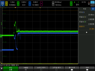
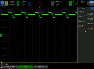
When the power of the product is supplied to the power supply, inrush current occurs, and the product does not operate afterwards.

It is reported that a higher inrush current occurs during the test after mounting on the actual vehicle, and it is reported that the product is dead and does not operate again.

[Iin : Inrush Current, yellow]

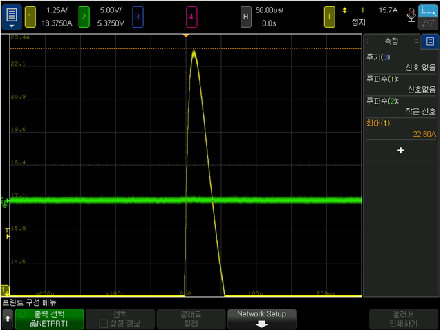
[Vin : Blue, Vout : Green]

Are there any defects caused by inrush current?

There seems to be no comment on Inrush in the datasheet, but if there is any data related to Inrush Current, please forward it.

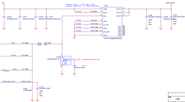
In addition, we will share the circuit diagram, so please review it.

Thanks.

Regards,

MJ

  • Hi MJ,

    Thanks for contacting us. It looks like the current limit resistor used is out of range - the range for Rilim is between 5k to 25k. While the Rilim is out of range, the default current limit will be 22A for B version, and thus what you see in the first screenshot. I will suggest you start with 25k, and only use one output port first and make sure the device is functional, and then you can adjust the Rilim value and number of output ports that fit your application.

    What's the Vbb voltage in this case? I wonder if the large power dissipation caused by 22A of current damaged the device (inrush happens fast before thermal protection kicks in). Have you tried to power cycle the device and it still won't work?

    Regards,

    Yichi

  • Hi, Yichi

    Thank you for your reply.

    VBB=12V.

    Most of the parts that are actually mounted on the car do not work again.

    However, if the test is performed using DC SUPPLY from outside, it may work again.

    Please explain in more detail what needs to be checked.

    Is the symptom of malfunction that can be caused by Inrush Current?

    The datasheet explains most of the Current Limit function, but there is no explanation for Inrush Current.

    Is there a function that IC protects when inrush current occurs?

    Thanks.

    Regards,

    MJ

  • Hi MJ,

    The current limit functionality is intended to limit the inrush current as well. As I pointed out in the previous post, the Rilim resistor used now is out of range, which means the current limit now is 22A. First thing to try is to change the Rilim to 20-25kohm and test again.

    Another possibility for the damage is that the supply will be dipping with such large inrush current, and the circuit will run into UVLO from DCDC converter side. The behavior might be unpredictable. 

    To summarize, first change the Rilim resistor and test the input current; and also monitor the supply voltage as well to see if it's dropping too much.

    Let me know if this makes sense to you.

    Regards,

    Yichi

  • HI Yichi

    I will let you know the current situation.

    1. VBB is B+ (car batterry 12V) or similar situations Power Supply.

    2. If I turn off and turn the power after such a situation occurs, it operate normally.

    3. R1154 (RILIM) is now in NC (No Connect) State.

    4. Immediately situation after Power ON [Vin_ : Blue,ut : Green] (Vout Fault situation)

    5. Vout in case of power Power failure

    6. Can TPS1HB35 return to normal operation after power stabilization ??

  • Hi Hyunsoo,

    Leave Ilim floating (without connecting a resistor) will set the current limit to highest value, and enter fault state automatically. I would suggest you use resistor from 5-25 kohm for Rilim. 

    As you connect Latch pin to ground with resistor, it will trigger the device to be in latched mode once fault occurs. If you want to have auto-retry mode, leave the Latch pin floating.

    Regards,

    Yichi

  • HI Yichi

    Rilim : 5.1k

    Latch is floating.

    inrush current is 21A

    Situation is same.

    No automatic recovery. Vout is equivalent to waveform 5 above.

  • Hi Hyunsoo,

    When I look at the waveform more closely, actually it's doing the auto-retry as the Vout is changing every 2ms, which matches the auto-retry period. One thing I'm thinking is the combination of current and voltage hit the device energy limit every time when it's trying to restart. 

    Could you try higher Rilim resistor such as 20k, and reduce the number of output channel used to reduce the current? I'm not sure if you are capable of reading the FAULT pin - that will give us extra information.

    Thanks!

    Regards,

    Yichi

  • HI Yichi

    Wouldn't the current limit be smaller if we use Rilim more than 20k?

    I use 5.1k

    What does it mean to reduce the number of output channels?

    What should I do with the latch pin to try again? Pull Down? Floating??

    Regards

  • Hi Hyunsoo,

    Yes use bigger Rilim would lower the current limit. The current limit would allow the part to operate; in addition to current limit, there is energy and thermal limit that will shut down the part once the limit is hit.

    I'm trying to see if it's actually the energy limit that prevent the part from starting, and thus I want to try 25k resistor.

    Could you try this first and see if it helps?

    For latch pin, either pull down or floating should give you auto-retry. I wasn't aware the auto-retry was happening.

    Regards,

    Yichi

  • HI Yichi

    Rilim : 25k

    Latch : Floating

    It's the same situation that doesn't work normally in the setting above.

  • Hi Hyunsoo,

    Could you capture the input current along with input and output voltage in the same screen capture?

    Regards,

    Yichi