This thread has been locked.

If you have a related question, please click the "Ask a related question" button in the top right corner. The newly created question will be automatically linked to this question.

BQ76952: Maximum uncalibrated current measurement accuracy

Part Number: BQ76952

Hello - I am trying to figure out what the maximum theoretical accuracy of the BQ76952 current measurement is without calibration.

My design is using a 1mOhm current sense resistor (1%, 75ppm temperature coefficient).  I am testing using a current limited power supply set to 50A output.

When I calculate the maximum theoretical accuracy at 50A, given the parameters in the datasheet, I find the maximum error @ 25C should be between -1.55A and 1.17A.  But when actually running 50A through the board, the AFE is reporting 54.77A.

My error calculations:

  • Rsns_max = 1mOhm + 1% = 1.01mOhm
  • VREF2_max @ 25C = 1.25V
  • LSB_max = VREF2_min / (5*2^15) = 7.63uV
  • Gain_max = 132,335 * LSB / 1V = 1.00964
  • VCC_offset_max = 1 * LSB = 7.63uV
  • VCC_offset_drift_max = 0V @ 25C
  • INL_max = 22.3 * LSB = 170uV
  • DNL_max = 0.1 * LSB = 0.763uV

Vmeasured_max = Current * Rsns_max  * Gain_max + VCC_offset_max + INL_max + DNL_max

= 50A * 1.01mOhm * 1.00964 + 7.63uV + 170uV + 0.763uV = 51.17mV

Icalculated = 51.17mV / 1mOhm = 51.17A --> 1.17A maximum error

Following the same process for negative error, I find -1.55A is the maximum negative error I should see when applying 50A.  But as noted above, I am seeing 4.7A measurement error.

Am I missing something in my calculations?

Thank you for your help,

Jessica

  • Hi Jessica,

    This error seems rather large - I wonder if there is some additional effect due to trace / via resistance that could be affecting the total sense resistance. Can you measure the current reported at different current values (see if there is a constant gain error)? 

    If the error tracks with gain and if the performance is consistent on more than one board, then this makes it easy to use the same CC Gain calibration value on every board. 

    Best regards,

    Matt

  • Thank you for the quick response Matt. 

    Here are the results at different current levels:

    Power Supply [A] AFE [A]
    AFE / Power Supply Ratio
    20 21.7 1.085
    25 27.02 1.0808
    30 32.58 1.086
    35 38.05 1.087142857
    40 43.67 1.09175
    45 49.2 1.093333333
    50 54.77 1.0954

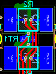
    The signals are routed differentially, so I would hope that trace/via resistance wouldn't have too big an impact.  I am using two current sense resistors (each 2 mOhm), with the sense traces routed to each resistor through a pair of vias (there are no other vias, it's a straight connection from there to the AFE input).

    Can you tell me whether my calculations for the maximum theoretical error for an uncalibrated current measurement are correct?  

  • Hi Jessica,

    I don't know where the error is coming from, but it is clear you should adjust the CC_Gain parameter to account for this ~9% gain error. Then your measurements should be much more accurate. 

    I do not think the error calculation is correct. I think the worst case error would be when measuring a max of 200A with a 1mOhm sense resistor because the error is dominated by gain error:

    If the full 200mV range with a 1mOhm sense resistor (so +/-200A current) is used:

    You can sum the worst-case offset, gain, DNL, INL, to get a worst-case error.

    The worst-case offset is 1-LSB + 0.03LSB/C*[(+25C)-(-40C)] = 1-LSB + 1.95-LSB = 2.95-LSB.

    The worst-case gain is error (assuming we ignore their sense resistor) is (132335 – 131454) *200mV = 176.2-LSB.

    The worst-case DNL is very small, we only spec typ, but assume 1-LSB. The worst-case INL is 22.3-LSB.

    So summing them all gives 202.45-LSB. 

    1-LSB = 7.6uV, so this corresponds to 1.539mV.  With a 1mOhm sense resistor, this corresponds to 1.539A error.  Note this assumes the sense resistor is perfect, and its value matches the values entered for CC Gain and Capacity Gain in the BQ76952 device.

    This error is dominated by gain, so it is worst at max current (when running 200A of current). If instead you only use +/-50mV of range, then the 176.2-LSB drops by 4x, and the current error becomes 70.3-LSB or 534mA with the 1mOhm sense resistor.

    Note that you need to take into account the accuracy, drift, and nonlinearity of the sense resistor as well.

    Best regards,

    Matt

  • Thank you for the detailed response, Matt.

    This mostly makes sense, but I do not see where the error in the LSB value itself factors in (being a function of VREF2, which itself has some error and a temperature drift, per Table 7.14).  Intuitively it seems like that should be factored into the Gain factor, but I'm not sure how to apply it in your example.

    As for adjusting the 9% error for my board: that definitely makes sense for a one-off, but I'd like to know how bad the current sensor theoretically could be without any calibration for future boards.  

  • Hi Jessica,

    I suspect that the 9% error is a function of the board layout and that you should find it is consistent when you check other boards with the same design. Have you tested the current measurements on a 2nd board?

  • Hi Matt,

    It does look like the gain error is consistent across multiple boards.  

    It still seems a little odd that the layout could introduce such a big difference, especially since it's routed differentially.  Are there any tips for better layout of the current sense traces?

    Thanks and best regards,

    Jessica

  • Hi Jessica,

    That is good that it is consistent across multiple boards since this is an easy adjustment to the CC Gain parameter for all boards. I am not sure what is causing the gain error on your board. There are some layout guidelines in the datasheet but they are not too specific.

    Best regards,

    Matt