This thread has been locked.

If you have a related question, please click the "Ask a related question" button in the top right corner. The newly created question will be automatically linked to this question.

BQ25700A: Charging Calibration

Part Number: BQ25700A
Other Parts Discussed in Thread: BQ40Z50, BQSTUDIO

Hi, I'm using the BQ25700A to charge a battery. I have it connected to a Raspberry Pi, and I'm sending it SMBus commands to do so.

Now, when I start charging the battery from <3 V, the charger always outputs a slightly lesser current than what I send. For instance, if I send 128 mA to the charger through the command, it outputs around 113mA. For 320mA, it outputs around 300mA. As soon as the battery crosses around 3V, the current goes up to the correct value. I'm not quite sure how to fix this, and was wondering what settings in the charger I can change. 

The other issue I've been having is towards the end of the charging. The charging voltage is set to 4192 mV. I'd expect the charger to output CC until the battery reaches that voltage and then start tapering current in CV mode. What happens instead is that the charger starts to taper the current earlier, even before the battery reaches 4192 mV. 

I'd really like some help fixing these two issues. 

Thanks

  • Hi Dhananjay,

    Thanks for reaching out and let's work to solve your issues.

    1. How are you measuring the charging current level? Are you reading it on a DMM? 128 mA/113 mA and 320 mA/300 mA seems very close and it could just be a measurement error. As for charging current not being accurate at < 3 V, the BQ25700A has a current clamp at voltage < 3 V as the charger is in the pre-charge stage (if REG0x12[2] = 1 which is the default). 

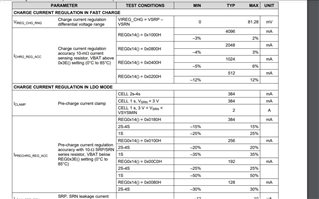
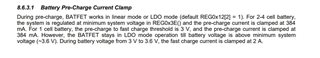
     *section 8.6.3.1 of datasheet

    Other than that, the current regulation will be less accurate in the pre-charge state than the fast charge state which the IC will enter at 3 V. You can view this at page 10 of the datasheet. 128 mA/113 mA and 320 mA/300 mA seems acceptable to me in LDO mode.


    2. Where and how are you measuring the battery voltage when the device start to go into CV mode? BQ25700A uses the SRN for battery voltage sensing and the IC will refer to the SRN pin value for operation. If you are sure that the battery regulation voltage is too low and want to raise the threshold, it is possible to change the regulation voltage through the MaxChargeVoltage (0x15) register.


    Hope this helps.

    Thanks,

    Peng

    *If my answer solves your question, please press "This Resolved My Issue" on the thread.

  • Thanks for the prompt reply Peng.

    1. I am reading the charging current and voltage both through a DMM and through a BQ40z50 gauge. I'm pretty sure this isn't a measurement error, since there is a pretty clear change in the current (both as measured by the gauge and the DMM) as soon as the battery crosses 3V. If I change the Minimium System Voltage to 2560 mV at REG0x3E, should that fix the issue? Basically, I'd like to ensure that I can specify the current manually over the entire battery voltage 2500 to 4200 mV. 

    2. Again, I'm using a DMM as well as a BQ40z50 to check the voltage. The issue with what you're saying is that I'm running a simple code with constant current, and was expecting the charger to taper the current on its own at 4200 mV. The error is much more noticeable at higher currents, since the charger starts to taper even earlier. I believe the SRN is probably miscalibrated, because of which the charger starts to taper the current before the battery actually reaches that voltage. Is there a way to address this? 

  • Hi Dhananjay,

    I changed my response and I think it somehow occurred at the same time as you are typing. 

    1. I changed my response a bit (just before your replied). When the part is in pre-charge mode and the battery voltage is < 3 V, the charge regulation will be less accurate. The variation could be as much as 50% as listed on the EC table on page 10. This is by design. 

    2. From your description, I think it is possible that at a higher current level, there are higher energy and therefore more noises get coupled to the SRN pin leading to less accurate voltage regulation. These types of issues are very sensitive to layout and circuit parasitics. I would recommend adjusting the SRP/SRN filter values and manually calibrate your system by changing the regulation voltage through MaxChargeVoltage (0x15) register. 

    Hope this helps,

    Peng

    *If my answer solves your question, please press "This Resolved My Issue" on the thread.

  • Thanks for the help Peng. 

    1. I was able to resolve the first issue with regards to the clamped current. Reducing the VSYSMIN did the trick.

    2. However, for the second one, I think I should've mentioned that I'm using the BQ25700A-EVM. I don't think I can install any additional capacitors. How exactly do I adjust the ACP/ACN filter values? Or, is there any other calibration I can do through BQStudio?

  • Hi Dhananjay,

    I did some testing in the lab as well as discussed with another team member. Here are the conclusions:

    1. Glad it solved your issue. I also did some testing in the lab. It seems that even in the 1S setting, lowering the minimum system voltage put the charger out of pre-charge state and therefore leading to more accurate current regulation.

    2. At higher charge current, the voltage (as V=IR) detected by the IC's SRN pin will be higher due to the parasitic (trace impedance, battery pack protection FET resistance, internal resistance in the battery or any energy storage device, etc.) in the system. The key is to minimize those parameters as the IC will determines its operation based on the detected voltage at the SRN point. However, this will only affect the charge speed but not the final storage potential of the battery. As it starts to taper, charger current goes lower and therefore the V=IR drop will be lower as well. Eventually, both the charge current and parasitic drop will be at its lowest and the battery will be charged to its full potential.

       In a production design, it may be possible to calibrate the system for a more accurate regulation point by using a huge amount of data points. However, that calibration is performed by the product manufacturer and is unrelated to the IC itself. For a prototyping design, this may not be necessary.

    Hope this helps,

    Peng

    *If my answer solves your question, please press "This Resolved My Issue" on the thread.