This thread has been locked.

If you have a related question, please click the "Ask a related question" button in the top right corner. The newly created question will be automatically linked to this question.

TPS62132: Schematic Design

Part Number: TPS62132
Other Parts Discussed in Thread: TPS62086, TPS62903, TPS61232

Hi,

I designed a step down converter for the 4G module. A regulator like the TPS62086 would have been easier, but I had to choose the TPS62132 because it was not in stock. The red area was the design proposed by Webenc Power designer. I put in other capacities as they suggest in their 4g module schematics (tantalum or other seramic capacitors)
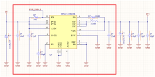

Max input 5.5V,
- Do I have problems with issues such as ripple voltage at 3.3V output or voltage values of tantalum capacities?
- Are there any other issues I should pay attention to in the diagram?
- Apart from that, are there any issues that I need to pay attention to while drawing the layout?

Best regards,

Mehmet

  • Hi Mehmet,

    The schematic looks fine. The output capacitance is on the higher side so you need to ensure stability by checking load transient and bode plot response on your design. Another thing is with a low input voltage range till 5.5V, the TPS62132 will have plenty of switching frequency variation from 500kHz to 2.5MHz. Please see figure 26 in datasheet https://www.ti.com/lit/ds/slvsag7e/slvsag7e.pdf#page=21 You need to make sure that works for your application requirements. For layout guidelines, I would recommend checking section 11 in datasheet on page 30.

    I would recommend taking a look at the newer TPS62903 which should also work for your specification. 

    Thanks,

    Amod

  • Hi Amod,

    A1) The output capacitance is on the higher side so you need to ensure stability by checking load transient and bode plot response on your design.

    Q1) Since I will feed the 4G module, there is an expression in the datasheet of the 4G module. ''the power supply must be able to provide a rated output current of 2.7A at least, and a bypass capacitor of no less than 220µF with low ESR should be used to prevent the voltage from dropping.'' and ''100nF,33pF,10pF'' Can you help me understand what you are saying? what should I do?

    A2) Another thing is with a low input voltage range till 5.5V, the TPS62132 will have plenty of switching frequency variation from 500kHz to 2.5MHz. Please see figure 26 in datasheet https://www.ti.com/lit/ds/slvsag7e/slvsag7e.pdf#page=21 You need to make sure that works for your application requirements.

    Q2) Section 8.3.5 says that 'Running with lower frequency a higher efficiency, but also a higher output voltage ripple, is achieved.' I wanted to work at 2.5MHz because I wanted to achieve lower output voltage ripple. Am I thinking wrong?

    The TPS61232 seems more reasonable due to the fixed 3.3V option at the output and the product is in stock.

    The TPS62903 is out of stock somewhere like digikey. When can I see high quantities in stocks? (Digi-key, mouser, etc.)

    Regards,

    Mehmet

  • Hi Mehmet,

    You can use the output cap as per the module requirements. On the requirements of output cap, the TPS62132 application information section lists the recommended L and Cout which is typically 2.2uH and 22uF respectively. Since you are on the slightly higher side of the max listed 200uF, I was recommending checking stability of the TPS62132 under a load transient event (where you step up and step down the load current) and ensure there is no ringing on the waveforms. An example waveform is on page 23 fig. 37 of datasheet. Based on my experience, the output cap requirement should be fine.

    Yes, the frequency will vary with input voltage so at lower inputs you might not get the 2.5MHz you are looking for. At 5.5V, you might be closer to ~2MHz-2.2MHz. Yes, efficiency will improve with lower frequency but ripple will be higher. 

    For out of stock question, I would recommend to contact the customer support center

    Thanks,

    Amod