This thread has been locked.

If you have a related question, please click the "Ask a related question" button in the top right corner. The newly created question will be automatically linked to this question.

BQ25611D: Application inquiry boost and charge mode

Part Number: BQ25611D
Other Parts Discussed in Thread: BQ25618, BQSTUDIO, ,

Hello Team,

My Customer has developed some sample boards using BQ25166D battery charger. They are getting some trouble understanding the switch between boost and charge mode.
The datasheet on page 34 : In boost mode , Q1 is always fully on too, regardless of this bit setting. But at page 46 it also say "During high current output over 700 mA in boost mode, a 10-kΩ pull-down resistor on VBUS is recommended to keep VBUS low in case Q1 RBFET leakage gets high"... so it seems with this sentence that Q1 should be off and not ON.

Moreover at pag 33 "In charging case application, based on adapter plug-in or removal, the charger will automatically transit between charging mode and boost mode by setting BST_CONFIG bit and "CHG_CONFIG bit both to 1." So again it seems Q1 should be off (elsewhere how can device between the two different mode ? ) like in the similar device BQ25618.

After some test on the board, it seems Q1 is fully on if boost is enabled. Is it correct?
How can we get and switch between charging and boost mode, once the adapter is inserted?
Can the device do it automatically?

Regards,

Renan

  • Hello Renan,

    Let me check with a colleague and get back to you tomorrow.

    Sincerely,

    Wyatt Keller

  • Hello Renan,

    Q1 should be fully on in BOOST mode as stated on page 34.

    For your last two questions: when both the BST_CONFIG and CHG_CONFIG = 1 then the charger will automatically switch between BOOST and BUCK modes

    Sincerely,

    Wyatt Keller

  • Hello Wyatt,

    Good day, actually the boost is working, the charge is working, and yes Q1 si fully on as expected, but even if they set both BST_CONFIG and CHG_CONFIG = 1 the IC is not auto switch from boost to charge.
    They periodically shut down the boost to make the IC able to detect the adapter is attached.
    Maybe is there some other parameter in another register to be set?

    Regards,
    Renan

  • Hello Renan,

    The charger should switch between modes with this setting unless there is a fault condition or timer expiration. Can you share their exported registers from bqStudio?

    Sincerely,

    Wyatt Keller

  • Hello Wyatt,

    Actually, my customer is working on their board at moment, they could switch back to Evaluation Board on Monday and check with bqStudio. By the way, attached is the register dump, please let me know if you see something strange.

    Regards,

    Renan

  • Hello Renan,

    If I'm reading the output correctly where the array numbering is equivalent to the registers, then it looks like the CHG_CONFIG bit is set to 0, so the charger will not switch from boost to charge until that bit is set.

    Sincerely,

    Wyatt Keller

  • Hello Wyatt,


    Good day.

    Sorry my customer noticed a small bug in printing the dump... all registers where shifted of 1 position so register 1 was in position 0, please refer to the correct image below.


    You'll notice register 1 is 52 value (0x34) so this should be both CHG_CONFIG=1 and BOOST_CFG=1.
    Actually is what is happening, both are working but it does not work autoswitch
    Please let me know if you find something strange

    Regards,

    Renan

  • Hello Renan,

    For the bq25611D it should automatically switch between the modes as long as all the conditions are met. Is the CE also pulled low?

    So to clarify, the charger will be operating in BOOST mode with both CHG_CONFIG and BST_CONFIG set to 1. Then the adaptor is connected it remains in BOOST mode instead of switching to charging?

    Can you share scope captures of the VBUS, VBAT, VSYS, and VSW when the adaptor is plugged in?

    Sincerely,

    Wyatt Keller

  • Hello Wyatt,

    I got feedback from our customer see the message below.

    "I connect the adaptor and the IC seems to remain in boost mode instead of switching to charging (actually I'm not sure of the mode, the IC seems to stop switching but I can't see just 10-20mA flowing from the adapter, by i2c I'm not able to read adpator presence).
    If I send an i2c command peridically to stop/start the boost (with a 300ms about of delay between the 2 commands), the charging start correctly (I see current flowing, I see by i2c that an adaptor is plugged and so on) .
    I took a look the signals you asked for:
    - VBUS it is at Vboost value before plugging the adaptor, than to 5V.
    - VBAT no changes, it remain constant
    - VSys no changes, it remain constant
    - Vsw, it change from switching to no switch (I attach you 2 pictures)

    CE is always pulled down with a 10K resistor."

    scope_capture.zip

    Your support is very appreciated.

    Regards,

    Renan

  • Hello Renan,

    I was able to test the issue with an EVM, I think I see the misunderstanding.

    The charger will switch from boost mode to charge mode and vice versa when both BST_CONFIG and CHG_CONFIG are 1. The BST_CONFIG will clear when the charger switches from boost to charge (No longer in boost mode). You will need to set the BST_CONFIG bit after the adaptor is plugged in so the charger will enable boost mode automatically when the adaptor is unplugged.

    Sincerely,

    Wyatt Keller

  • Hello Wyatt,


    Good day.

    I got a response from my customer and sorry but they don't understand how this to solve the situation. Further more I posted their response below:

    "When the board normally works I have to enable the boost, and the firmware could not know when the adapter will be plugged.
    The user decide to plug the adapter, but as the VBUS is polarized, I'm not able to understand this situation, the IC stop switching but I don't see any differences in the register dump before and after adaptor plugging.

    How to check adaptor presence once the boost is enabled?"

    Regards,

    Renan

  • Hello Renan,

    The registers dump should change after the adaptor is plugged in when the charger switches from boost mode to charging mode.

    From their testing they should see the BST_CONFIG bit reset to 0 when the adaptor is plugged in. The host just needs to set BST_CONFIG when it is reset when the adaptor is plugged in.

    Sincerely,

    Wyatt Keller

  • Hello Wyatt,

    My customer response is:

    In other words, what condition can make the charge not starting when the boost is enabled?
    Consider everything seems to work pretty well when they just set BST_CONFIG = 0, adapter is detected and charge is starting ... but if we set BST_CONFIG = 1 we see a constant situation in register dump as I sent you, with or without adapter.

    Regards,

    Renan

  • Hello Renan,

    The test I performed showed the following:

    • Connect battery simulator to BAT and load on VSYS.
    • Set both CHG_CONFIG and BST_CONFIG to 1.
    • 5V seen on VBUS from boost mode operation.
    • Connect adaptor of 5V, then BST_CONFIG clears and begins charge.

    But it sounds like even after you do the same the BST_CONFIG does not clear it does not begin charge?

    All your tests are with bq25611D?

    Sincerely,

    Wyatt Keller

  • Hello Wyatt,

    Good day.

    My customer response is:

    Yes now I'm making some test with bq25611DEVM, I'll attach you a picture.

    charge.zip
    Register 1 set to 0x30, if I attach the adapter I see 5V on VMID (instead of 4.6V of boost), but the charge does not start... no changes on registers.

    If I just unselect "Enable OTG" from BQStudio charge start correctly. I'm starting to think we could have a different version of the IC? I have BQ25611D REV ID 1.0 read from BQSTUDIO? Maybe there's a newer version? I'm wondering about a bug in this version?
    Regards,
    Renan
  • Hello Renan,

    There is most likely a hardware issue, I tested with the same register settings on the EVM on my bench, the charger always switches between modes. I have attached a picture of my testing. You can see the switches between modes:

    Regions:

    1. OTG disabled, adaptor unplugged
    2. OTG enabled, 4.75V regulation
    3. Plug in adaptor at 5V (set the OTG_CONFIG bit again to 1 in this region)
    4. Unplug adaptor - short pause between modes

    Sincerely,

    Wyatt Keller

  • Hello Wyatt,

    My customer is still confused on how could be a hardware issue since theoretically, he is using the same EVM board.
    Does your board has the same IC revision?
    Other possibilities?
    What could they do to give you more information so?

  • Hello Renan,

    Can you share the schematic of the board their using? Can you test with a different EVM to see if same issue is occurring? The charger should have the same characteristics, the revision, if there is one between our two chargers, should not influence the behavior.

    Sincerely,

    Wyatt Keller

  • Hello Wyatt,


    Good day and thank you for this response.

    My customer provided the schematic below:

    schematic_1.zip

    Also added the following message below:

    This is the schematic of my board, it has been done following your EVM. Also the board has been designed following the EVM so it should be almost similar. Unlucky I've only one EVM, but actually I'm afraid if I buy another one from my distributor I got the same result, as I replicated in almost 10 custom boards and 1 EVM (charge does not start untill I remove OTG_CONFIG bit).

    Regards,
    Renan

  • Hello Renan,

    Can they re-send the register export from bqStudio? I can try to replicate further with a different EVM, I want to make sure I had the same settings. I'll ask someone else on the team for their opinion as well on this issue.

    Sincerely,

    Wyatt Keller

  • Hello Wyatt,

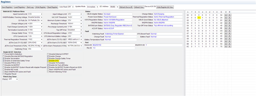
    Here you find the configuration my cusotmer test today; actually it is the default configuration, changing only regulation voltage to 4.6V and setting Enable OTG bit.
    I read correctly 4.6 on VBUS, I plug the adapter with 5V, I see 5V but charge does not start.
    If I disable the ENABLE OTG bit, charge start.

    (forgot to disable the Watchdog Timer)

    Regards,

    Renan

  • Hello Renan,

    I will get back to you on Tuesday.

    Sincerely,

    Wyatt Keller

  • Hello Wyatt,

    Good day. 

    I found this e2e thread and can you confirm that could you please double check quickly the situation ?
    Is BQ25611D auto switch really working or not ?
    If yes what can cause to not work even in TI EVM for my cusotmer?

    link: https://e2e.ti.com/support/power-management-group/power-management/f/power-management-forum/964851/bq25611d-bq25611d-connection-of-vac-and-vbus-pin

    Regards,

    Renan

  • Hello Renan,

    Ricardo is correct, the other devices (bq25618 and bq15619) are better suited for your application because of the PMID pin. I would follow this recommendation because the detection of an adapter on VBUS may not always work because VAC will have difficulty detecting the voltages that are so close.

    Sincerely,

    Wyatt Keller