This thread has been locked.

If you have a related question, please click the "Ask a related question" button in the top right corner. The newly created question will be automatically linked to this question.

LM5121: Webench suggestions for D1 seem very large (freewheeling diode, DF in datasheet)

Part Number: LM5121

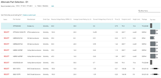
I noticed the diodes proposed by Webench for the freewheeling diode on the disconnection FET circuit seem to be physically huge on our design, unreasonably so (it seems to me).

As a sanity check I put into Webench the parameters for the reference design (or as close as possible) - ie 4.5-12Vin 12Vout 2A (webench won't support design down to 3Vin); and again the diodes are huge by comparison to what is actually on LM5121EVM - Diodes inc DFLS1100-7, a powerDI-123 package - roughly 6mm2.  By comparison, all the SMD parts suggested by Webench are >100mm2.

What's going on here?  Are the parts suggested by Webench way oversized, or is the reference board not adequate?  I can't see anything obviously different about the reference board which suggests such a difference.

The large parts suggested by Webench are going to be pretty annoying to layout if they're really necessary, but of course if we must then I would try to find space for them.

Any assistance much appreciated.
  • Hello AJMES FINNIE,

    The EVM selection should be good. Please refer to the datasheet 8.2.2.19 for the diode selection guidelines. The Webench design gives you a starting point but the device selection could be an overkill.

    Thanks,

    Yinsong

  • Hi Yinsong,  Many thanks for the note on this and taking the time to reply. 

    Can you share the logic behind such large device selection for this part in Webench?  Now I look in detail at the selections, I'm equally a bit surprised by how small the disconnect FET selections are, compared to the very large FET used on the reference!

    I found this supplementary doc (https://www.ti.com/lit/pdf/snva726) which also deals with these topics; I note it suggests 160mV/Rs to size the diode, rather than 150mV/Rs from the datasheet, I guess the difference is small, but begs the question why different. 

    I suppose the worst case for the freewheel diode is if the system enters some overcurrent situation where the hiccup circuit comes into play, repetitively stressing the diode by starting up and shutting down the PSU over and over, and the worst case for the input disconnect FET is the circuit breaker case mentioned above?

    Can you confirm is webench doing the calculations to ensure the disconnect FET can withstand Eshort and Ecb?

    It's a shame that Webench doesn't give a bit more information in the design report as to which calculations have been performed with the parts proposed.

  • Hi AJMES FINNIE,

    The application report you found is good. Please refer to this one instead of the Webench if you are not sure. The 160mV/Rs is based on the typcial value of VCS-TH3 in the datasheet. Yes and the worst case of the diode should also consider the non-repetitive surge current in the circuit breaker scenario. Sorry for the confusion but again, the Webench just gives the power designer/engineer a starting point. Please let me know if there is any question.

    Thanks,

    Yinsong