Dear TI Team,
I am working on embedded wearable device powered with 300mAh Lithium battery.
We are updating device design from prototype to consumer-grade. Currently, we are redesigning the battery related components to meet the safety aspects.
We try to follow IEC 62368 as a guideline, and the system(not the battery pack) has to meet following requirement:
"for rechargeable batteries, charging and discharging at a rate exceeding the battery manufacturer’s recommendations, and reversed charging are prevented".
I have following understanding regarding what is needed from the system to protect the battery & user:
1) There should be reverse current protection from battery to external charging USB port.
2) During charging:
- Overvoltage protection that may originate from external power source.
- Overcurrent protection that may originate from external power source.
3) During discharging:
- Overcurrent protection that may happen during short in the load
- Undervoltage protection to disconnect the battery when it falls below ~3.0V.
4) Lastly, charging should be stopped if temperature is too high or low.
We decided to use BQ 24230 charger IC. It has reverse current protection. It also has Ichg limit, and it doesn't charge beyond 4.2. It has NTC input
to terminate the charging at needed temperatures. Thus, this charger IC seems to cover 1, 2, and 4 safety aspects.
My first question, is my understanding correct up to this point?
Now, we need to cover aspects in point 3, i.e. protect the battery from overcurrent and undervoltage conditions. Also, we need a fuel gauge for application(not for safety).
So, I was looking through the TI products, and observed following:
1) System-side fuel gauges doesn't offer protection
2) Some pack-side fuel gauges offer protection, but we intend to use fuel gauge on the PCB, not on the battery.
3) There are separate battery protection circuits, which seem ok for our needs. But from the typical schematics, I have a feeling that they are intended
not for use in PCB, but as an integral component of battery pack. Am I correct? Or can we put them on PCB?
Next, both charger IC and fuel gauge need NTC input. We want to use battery's internal NTC for better accuracy. Is it ok to use single battery NTC both as input
for charger IC and fuel gauge?
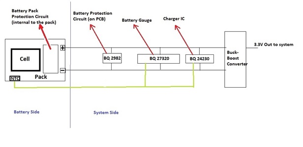
After all these thoughts, I am thinking about following topology. What do you think? Do you have any recommendations? Maybe it would be better to use combination of fuse & switch that opens circuit on low voltage instead of whole battery protector? If you agree, are there any TI products that you can recommend for this purpose?