Other Parts Discussed in Thread: UCC28180, UCC256403
The PFC part has been debugged separately in recent days, but other parts have not been welded.
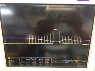
When the PFC is started for the first time, the PFCGD can also see 100kHz waveform, and there is no response when it is opened again.
The multimeter tests that the PFCGD is short circuited to GND (Pin1) of power ground, but not to AGND (pin6) of signal ground; Later, when the PFCMOS was removed and replaced with a new UCC29950, the PFCGD waveform did not respond. After the power off and discharge, the PFCGD was still short circuited to GND (Pin1). When the PFCGD was measured again after a period of time, it was normal, but there was no PFCGD waveform.
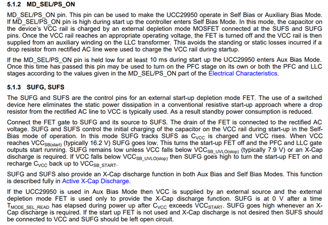
At present, the GND of AGND is connected by a 0R resistor.My current sufs and MD_ SEL/PS_ On is directly connected to VCC, and VCC is provided by a separate small board, sufg and AD_ Det is not connected with any components, and the small power supply board is not used for power supply in the debugging process. It is an external DC power supply.In addition, what are the layout requirements of IC signal ground and power ground?
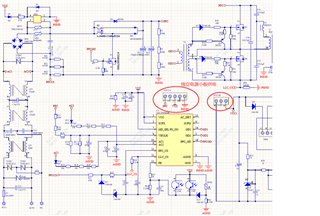
At present, I use a 0r resistor to connect, is GND (Pin1) to the electrolytic capacitor ground first or agnd (pin6) to the electrolytic capacitor ground first?