This thread has been locked.

If you have a related question, please click the "Ask a related question" button in the top right corner. The newly created question will be automatically linked to this question.

BQ76952: BQ76952PFBR short circuit protection issue

Part Number: BQ76952

Hi Team,


Customer is using BQ76952 and did a 12S BAT pack prototype, but during the short-circuit testing they found a issue that:

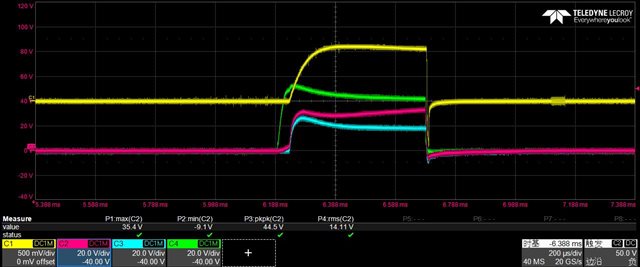
  • At short circuit status, BQ76952 DSG voltage will change to ‘High’ automatically ~every 6ms, which may cause the MOSFET be broken.
  • If short circuit protection be trigged, BQ76952 will change from ‘SEAL mode’ to be ‘UNSEL mode’ itself.
  • Enclose please also refer to the gg file and log information (bqz firmware version is 0.36).

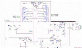
Attached is related part's schematic, log date & gg file, also the testing waveform as below, could your kindly check it and suggest what’s the potential reason & further experiment to verify the root cause?
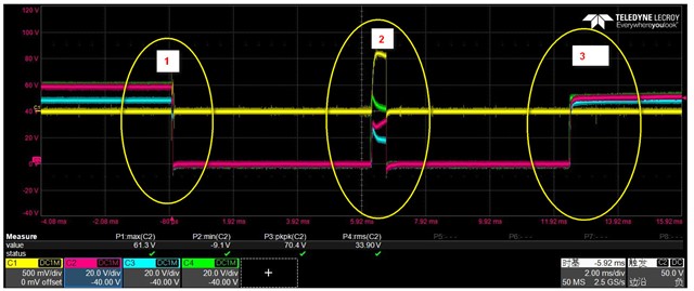
CH1:   of DSG_FET

CH2:  of DSG_FET

 of DSG_FET

 of BQ76952

CH1:   of DSG_FET

CH2:  of DSG_FET

 of DSG_FET

 of BQ76952

12s_bq76952_20210302.gg.csv log.CSV

  • Hi Cheney,

    The behavior is typical of a reset caused by SRP and SRN going high at the short circuit event. Be sure the design keeps SRP near VSS, recommended range is less than 0.75V.  A recent data sheet change added a description in the layout section for optional to add 0.1 uF caps to VSS near the IC.  This will help to avoid the reset if the design has large transients on SRP, SRN.

  • Hi WM,

    Noted and a update that customer already added the caps to VSS and below please related BQ76952 part's schematic.

    SCHEMATIC1 _ DF15_BAT-BMS.pdf

    Will check the resistor/transient voltages first, many thanks.

  • Hi Cheney,

    I see the capacitors, GND is represented on the cell side, the schematic does not show the physical construction, so checking the voltage during transient is suggested.  CE0 is shown connecting at that point through R127.  That connection is preferred since VC0 would reference VSS, but checking the transient on VC0 during the SCD would also be good, VC0 is recommended not to go below -0.2V, -0.3 is abs max.

    I see the pack side of the load resistor is connected to DGND.  If this rises suddenly due to the SCD it will push up the REG1 and REG2 voltages.  I don't know the effect on the BQ76952, the filter caps should be connected to VSS to avoid sudden changes to the pins.

    The top cell must be used on BQ76952.  So VC16, pin 48 should connect to R57, but VC15 to VC12 should connect to VC11.  Change the appropriate bits in the Vcell mode setting.  I don't expect this to affect SCD.

    The input filter capacitors are 0.1 uF, this is suitable if sufficient for the SCD transient.  Check that VC16 does not exceed ABS MAX  during the SCD transient.  We have used 0.22 uF on the EVM to avoid violation, with 12 cells you have more margin and the 0.1 uF with the 33 ohm input resistors may be sufficient.

    We recommend 100 ohm for the BAT filter resistor R18.  Check the transient at the BAT pin.

    C22 is shown as 0.1 uF, this should be 22 nF nominal.

    A capacitor may be desired on Q9 collector to avoid transients coupling from collector t emitter.  We typically show 1 uF, another value may be suitable, check if transients are coupled during the event.

    If transients are high at SCD turn off you might try slowing turn off speed of the discharge FETs by adjusting R155.  It is a tradeoff to have fast enough turn off to avoid damage risk to the FETs but slow enough to avoid a large inductive response from the cells and interconnect which may cause disruptive transients.