This thread has been locked.

If you have a related question, please click the "Ask a related question" button in the top right corner. The newly created question will be automatically linked to this question.

UC1843A-SP: PSPICE-FOR-TI : SIMPLE schema with UC1843A doesn't work while it was working with TINA

Part Number: UC1843A-SP
Other Parts Discussed in Thread: TINA-TI

¨Dear TI Teams,

I have tried to install and use PSPICE FOR TI but I'm strunglling simulating a ,simple circuit with the UC1843A-SP PWM controller. The schematics is shown below

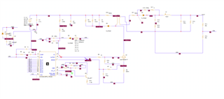
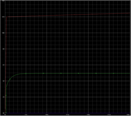
the UC1843A-SP is sup)plied and the FB voltage at start is 0V. The chip should start providing a PWM signal to the FET for hashing, but bothing is happening (blue curve belmow is the gate of the FET, wich stay at 0V).....

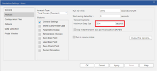
The chip doesn't seems to start at all. The simulation profile is very simple as follows (the rest  I didn't touch ) 100

This schematics is working fine with TINA-TI...

Can you help resolving this? The main motivation of moving towards PSPICE FOR TI is the simulation capabilities upgraded, like the monte carlo simullations and so on...

Thanks in advance.

JF.

  • Hi JF, 

    Thanks for bringing this to our attention and for sharing screenshots of your setup. I'll look into this today and get back to you as soon as I can.

    Thanks,

    Sarah

  • Hi JF,

    I recreated your circuit & simulation profile and saw the same behavior at the FET gate. Specifying the maximum step size as 50ns in the simulation profile appears to resolve the issue in my simulations. When this value is not specified the simulator sometimes takes steps that are too large and produces misleading results. Can you try this and let me know if it works for you?

    Thanks,

    Sarah