Because of the holidays, TI E2E™ design support forum responses will be delayed from Dec. 25 through Jan. 2. Thank you for your patience.

This thread has been locked.

If you have a related question, please click the "Ask a related question" button in the top right corner. The newly created question will be automatically linked to this question.

No voltage at Vdd Pin

Part Number: UCC28700
Other Parts Discussed in Thread: UCC28610, UCC24610,

I have a circuit that should be working at 5V, 4.2A. I just put the board together and noticed that I am not getting any voltage at the VDD pin. I have an bulk voltage of 150V and after the first 2Meg ohm resistor the voltage is 69V. However, after the second resistor I get 0V. What could be causing this? 

Thanks5V_4.2A.pdf
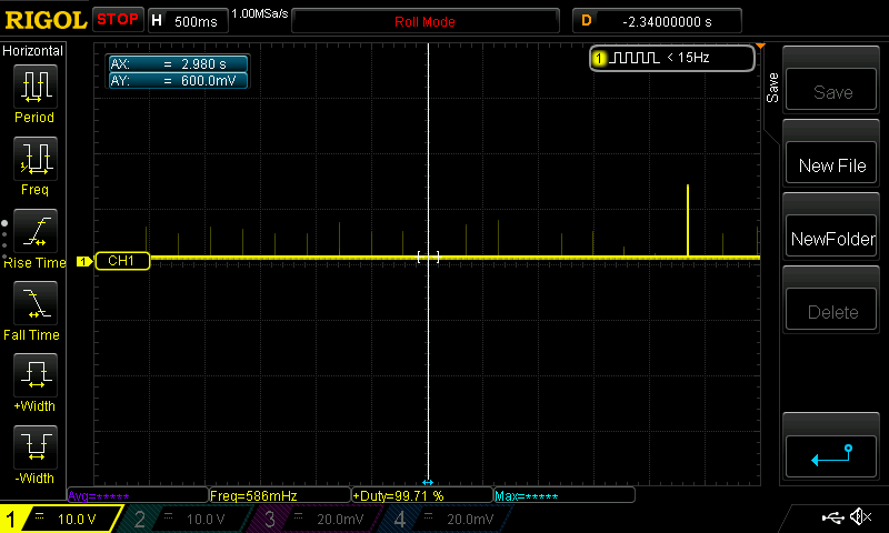
vddpinVDD

DRV pinDRV

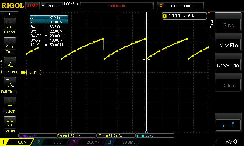
VS PinVS

  • Hagen,
    thanks for your interest in TI here. I've contacted an applications engineer to assist you with your question. You should hear from them today.
    Regards,
    John
  • Hello Hagen,

    I reviewed your schematic and have the following comments.

    1. There should be rectifier diode between pin 7 of the transformer and capacitor C8 and C9.

    2. There should also be a connection to pin 8 of the transformer and capacitor C8 and C9.

    3. You might consider using an RCD clamp instead of a Zener clamp.

      1. 499 k ohm resistor and 2.2 nF capacitor should work.

    4. I have marked up the schematic showing how these modifications should be implemented and have attached it for your reference.

    For this power level you might consider using a synchronous rectifier (SR) FET instead of a rectifier diode. We have a reference design PMP7389 that has an offline flyback converter with an SR design to step down an AC line of 85 V to 265 V RMS down to 5V, 5A to support a dual 5V output of 2.2 A X2.  This design uses the UCC28610 flyback controller and the UCC24610 SR driver.  You could use this flyback converter as starting point for your design if you wish.  It is close to the power level you are trying to achieve.  The following link will bring you to the reference design. http://www.ti.com/tool/PMP7389?keyMatch=null&tisearch=tidesigns-power

    In regards to your design not starting up there should be 150V/4 M ohms = 37.5 uA of current to trickle charge the VDD capacitor. The Istart current for the UCC28700 is only 1.5 uA maximum so there should be enough current to charge this VDD capacitor. It sounds like something is shorting the VDD pin to ground.  I would double check your layout and connections to see if there is anything shorting out the VDD pin.

    Regards,

    Mike

    5V_4.2A Marked Up.pdf

  • This design uses the ucc24610 and CSD17510 as the secondary rectification instead of a diode. I have had this design work previously. I just did a new layout of the board which is when it stopped working. I will try to check around and see if I can find anything that is shorting the vdd pin. thanks
  • I exchanged the ucc28700 chip and now I have other issues. The chip is going into fault mode and I can not figure out why. I will attach all of the images for reference. Any advice would help.