This thread has been locked.

If you have a related question, please click the "Ask a related question" button in the top right corner. The newly created question will be automatically linked to this question.

LM2576: LM2576T-ADJ/NOPB

Part Number: LM2576

Hi,

We have designed 24Vdc to 5Vdc supply using LM2576T-ADJ/NOPB IC. Layout and schematic is reviewed by TI. 

Problem Observed :

Sometime when we switched ON the unit only LM2576T-ADJ/NOPB part found damage rest components are fine.

Verified by replacing simply LM2576T-ADJ/NOPB with new part and circuit works.

Input parameter :

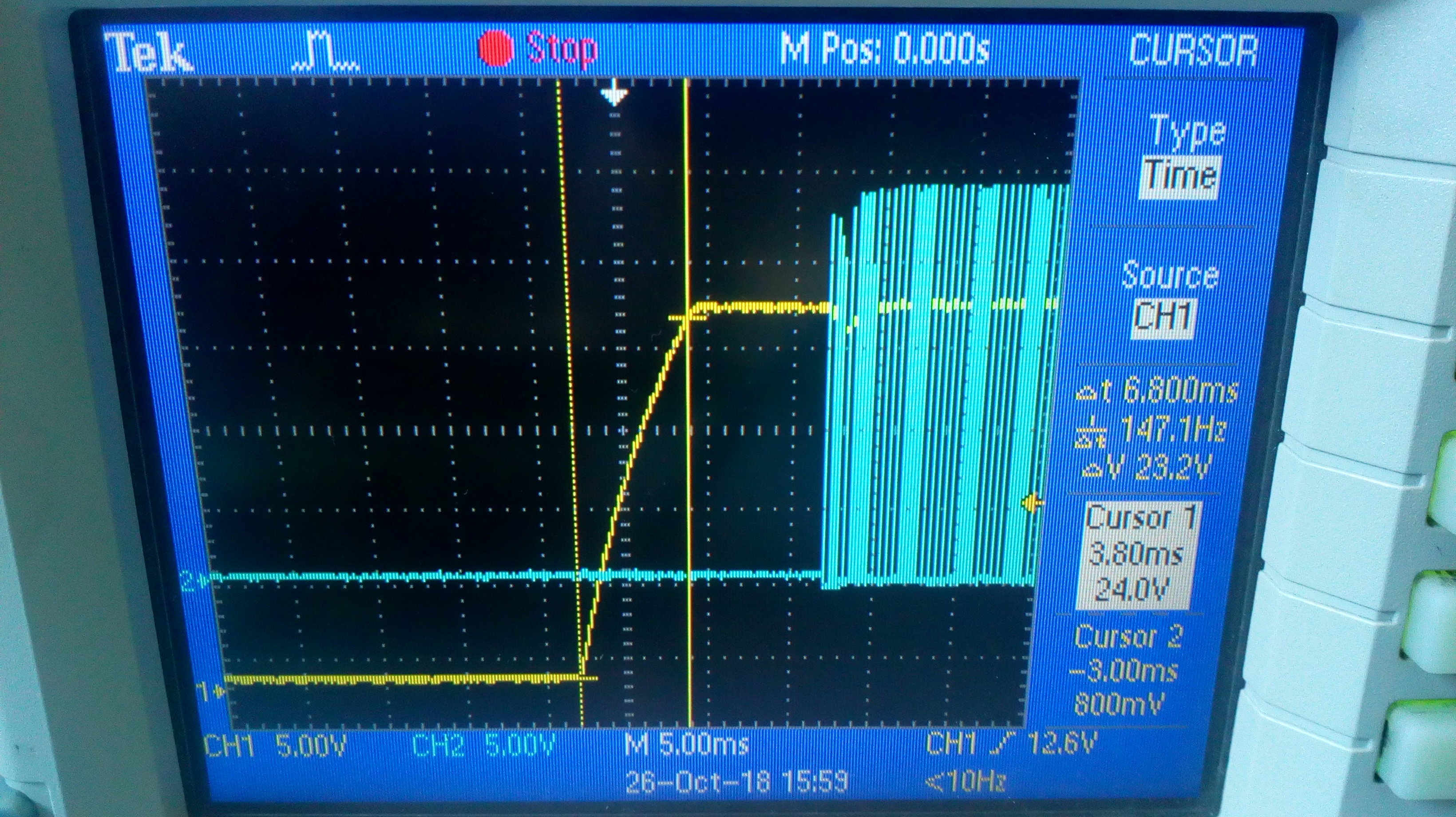
Voltage : 24Vdc from SMPS

Output Parameter :

Volateg : 5Vdc connected feedback resistor

Current : 2Amax. but 0.5A current load was connected when problem observed.

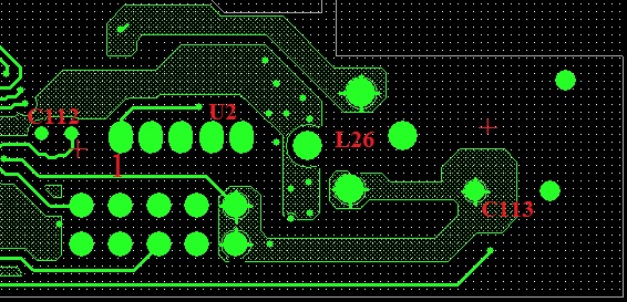
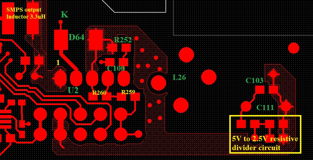
For refernce schematic attached.

Concerned area :

1) Inductance 220uH local make

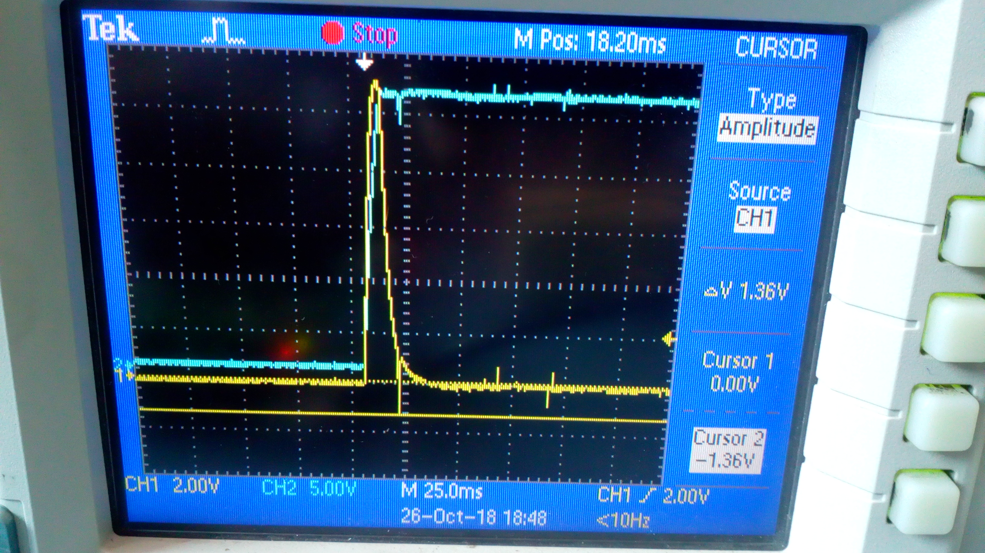
2) Delay circuit connected at Pin 5 and ground because it provides delay at the switing ON the unit.

LM2576T-ADJ/NOPB
  • Hello,

    Can you help answer some clarifying questions on this issue?

    1. Is this happening at the first start up? Is this a hot plug event? Are there long cables from the board to the power supply?
    2. Can you also share the component values for the components in your schematic?
    3. Can you share the layout?

    Thank you,
    Katelyn
  • Hello,

    Please find below reply,

    1. Is this happening at the first start up? Is this a hot plug event? Are there long cables from the board to the power supply?

    It is not happening every time we switched ON the unit.It occurs randomly.

    Supply is 230Vrms using which we generate isolated 24Vdc through SMPS which is then feed to LM2576 for generating 5V.

    Power supply is connected with other controle circuit using burg srtip.The only cable we use is to power the system 230Vrms and internal cable with connector for LED's from controller board to power board.

    2. Can you also share the component values for the components in your schematic?

    Please find attached image for component value and selected part number.

    3. Can you share the layout?

    Please find attached image for both Top and Bottom side layout

    Top View :

    Bottom View :

    Waiting for your valuable feedback.

    Thanks & Regards,

    Sachin S Chaugule

  • Waiting for valuable reply
  • Hello,
    Please provide feedback against provided details.

    Regards,
    Sachin S Chaugule
  • Hello Sachin,

    The input capacitor is very far from the device. The input capacitors should be directly next to pin 1 and ground. This is critical for the converter operation. There will be additional noise and ringing due to this large loop.

    Can you share a waveform of the input pin during start up? I want to see if there is a large amount of noise and ringing.

    Best Regards,
    Katelyn
  • Hello Katelyn,

    The input capacitor is placed near to IC pin 1 which is input pin.

    Please find attached images as below,

    Channel 1 : Input 24V Pin 1   and Channel 2 : Switching Point Pin 2 

    Channel 1 : Input 24V Pin 1   and Channel 2 : Switching Point Pin 2 

    Channel 1 : Input 24V Pin 1   and Channel 2 : Switching Point Pin 2 while turning ON

    Channel 1 : Input 24V Pin 1   and Channel 2 : Switching Point Pin 2 while turning ON

    Channel 1 : ON/OFF  Pin 5   and Channel 2 : Switching Point Pin 2 while turning ON

    Channel 1 : ON/OFF  Pin 5   and Channel 2 : Switching Point Pin 2 while turning ON

    Since the problem observed was during Turn-ON so can Pin 5 create issue.

    Will Pin 1,2 and 3 get short if Pin5 observes negative voltage?

    Probes connected using ring lead across Pin3 and Pin5 for last image but during Turning ON negative voltage greater then 0.3V observed.

    Thanks & Regards,

    Sachin  S Chaugule

  • Hello Sanchin,

    This is possible. Pin 5 should not see less than -.3V at any time. My recommendation would be to ensure Pin 5 does not see less than -.3V and that the input capacitor is as close to the input pin as possible. It is difficult for me to tell where the CIN component is in the picture of your layout.

    Best Regards,
    Katelyn