This thread has been locked.

If you have a related question, please click the "Ask a related question" button in the top right corner. The newly created question will be automatically linked to this question.

BQ76PL455A-Q1: The voltage of cell#12 is always higher than the actual value

Part Number: BQ76PL455A-Q1

Hi,

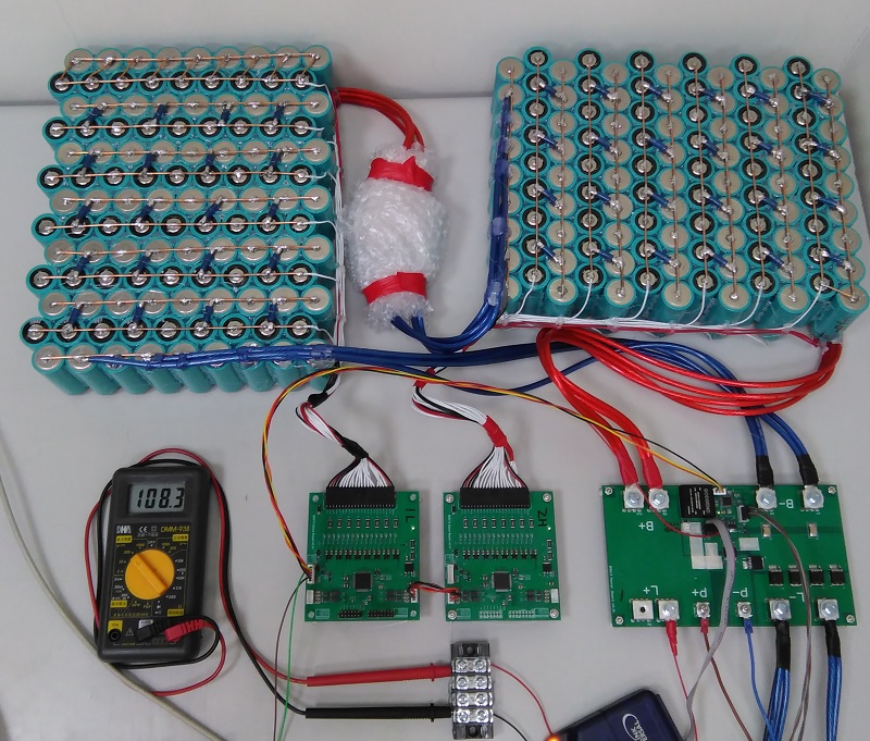
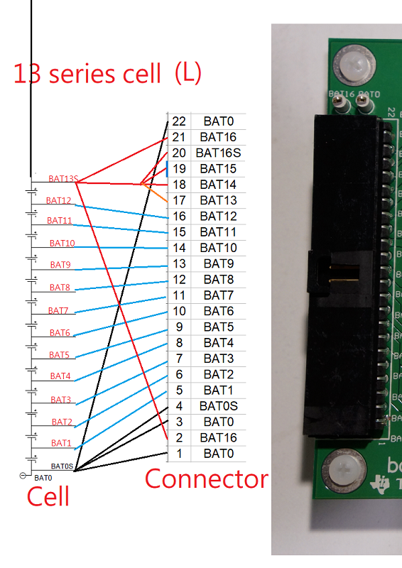
We use our own designed circuit board to manage 26-cell. Each board manage 13-cell.

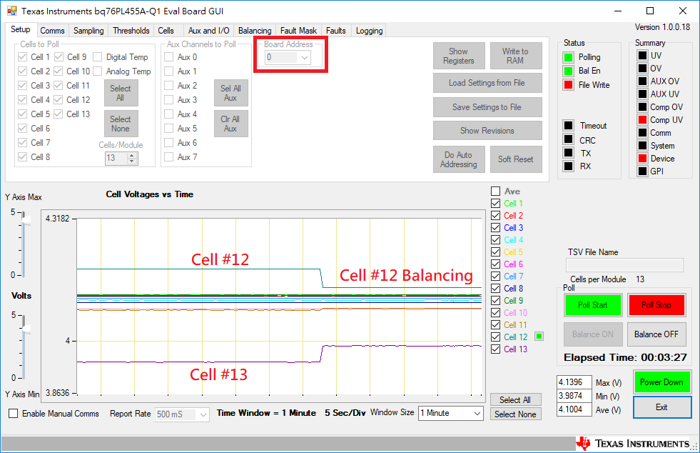
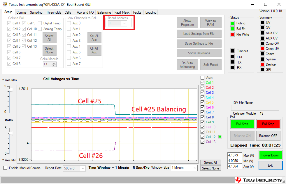
We have a issue that is voltage of Cell #12 always higher then the actual value, and Cell #13 always lower then the actual value.

Board #1 and board #2 are the same. Please see following picture.

Do you have any recommend?

Best Regards,

Aaron

  • Hi Aaron,

    Can you explain how you connected the unused VC pins (i.e. 13 shorted to 14,15,16) and are you connecting actual cells or using a resistor divider to simulate the cells? Are you balancing during the times you see inaccurate measurements?

    Regards,

    Taylor
  • Hi Taylor,

    We were connect actual cells.

    Best Regards,

    Aaron

  • Hi Aaron,

    Ok, can you please send the schematic of the board?

    Thanks,

    Taylor
  • Hi Aaron,

    Have you solved the issue?
    If not then share the schematic with Taylor.

    thanks

    Roger
  • Hi Roger,

    No. The issue persist.

    Our schematics as attachment.B0013_Slave_v002_Sechemastics_01-04.pdf

  • Hi Aaron,

    I reviewed the schematic.
    What is cap value for OUT pin?

    Use 390pF ONLY and recommended register settings are in the Datasheet.
    Please follow our recommendation with 390pF out cap.

    Roger
  • Hi Roger,

    We mount R57 for 390pF out cap show as following:

    Best Regards,

    Aaron

  • Hi Roger,

    My code as following:

    main(){
    
    .....
    
    PL455_Reboot();
    
    PL455_ClearFault();
    
    PL455_AutoAddress();
    
    PL455_EnableCommunication();
    
    PL455_SetBaudrate();
    
    PL455_SetCommunication();
    
    PL455_ClearFault2();
    
    PL455_SetAFE();
    
    PL455_SetOVUV();
    
    PL455_BrocastRequest(bFrame); // Measure Cell Voltage
    
    ......
    
    }

    void PL455_SetAFE(void)
    {
    	for(nDev_ID=0;nDev_ID < TOTALBOARDS;nDev_ID++)
    	{
    		// Configure AFE (section 2.2.1)
    		nSent = WriteReg(nDev_ID, 60, 0x00, 0x00, 1, FRMWRT_SGL_NR);	// 91 00 3C 00 3D FC ==> set 0 mux delay
    		nSent = WriteReg(nDev_ID, 61, 0x00, 0x00, 1, FRMWRT_SGL_NR);	// 91 00 3D 00 3C 6C ==> set 0 initial delay
    
    		// Configure voltage and internal sample period (section 2.2.2)
    		nSent = WriteReg(nDev_ID, 62, 0x00, 0xCC, 1, FRMWRT_SGL_NR);	// 91 00 3E CC 3C C9 ==> set 99.92us ADC sampling period
    
    		// Configure the oversampling rate (section 2.2.3)
    		nSent = WriteReg(nDev_ID, 7, 0x00, 0x00, 1, FRMWRT_SGL_NR);		// 91 00 07 00 2E CC ==> set no oversampling period
    
    		// Clear and check faults (section 2.2.4)
    		nSent = WriteReg(nDev_ID, 81, 0x00, 0x38, 1, FRMWRT_SGL_NR);	// 91 00 51 38 10 BE =====> clear fault flags in the system status register
    		nSent = WriteReg(nDev_ID, 82, 0x00, 0xFFC0, 2, FRMWRT_SGL_NR);	// 92 00 52 FF C0 59 AC ==> clear all fault summary flags
    	}
    
    	// Select Identical Number of Cells and Channels on All Modules Simultaneously (section 2.2.5.2)
    	nSent = WriteReg(0, 13, 0x00, 0x0D, 1, FRMWRT_ALL_NR);				// F1 0D 0D 94 A6  =====> set number of cells to 13
    	nSent = WriteReg(0, 3, 0x00, 0x1FFF03C0, 4, FRMWRT_ALL_NR); 		// F4 03 1F FF 03 C0 66 30 ==> select 13 cell, AUX channels 0 and 1, and internal digital die and internal analog die temperatures
    }

    Is my code wrong?

    Do you have any remmend?

    Best Regards,

    Aaron

  • main(){
    .....
    			PL455_Reboot();
    			PL455_ClearFault();
    			PL455_AutoAddress();
    			PL455_EnableCommunication();
    			PL455_SetBaudrate();
    			PL455_SetCommunication();
    			PL455_ClearFault2();
    			PL455_SetAFE();
    			PL455_SetOVUV();
    
    			for(i=0;i<120;i++)
    				bFrame[i]=0;
    			PL455_BrocastRequest(bFrame);			// Measure Cell Voltage
    
    .....
    }

  • Hi Aaron,

    The schematic looks okay, can you please check this with the following settings for best accuracy?

    The recommended settings for best accuracy are:

    - 16 cell channels

    - 390pF OUT filter cap

    - AFE_PCTRL = 1 (causes 100us for ADC power up)

    - Cell ADC sample period = 60us

    - Cell ADC sample period for oversamples = 12.6us,

    - Staying on a cell channel to oversample

    - AUX ADC sample period = 12.6us

    - 8x oversampling of CELL and AUX channels

    Regards,

    Taylor