

Hi,
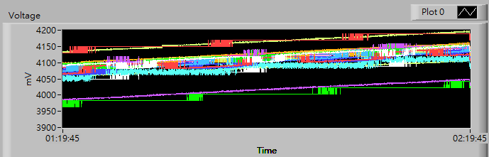
We are using BQ76PL455A-Q1 *2 for 26 series cell. The chart below shows the voltage(26 cells) of charging.
Why are some cells with a linear voltage, some of which are step-by-step?
Hi,
We are using BQ76PL455A-Q1 *2 for 26 series cell. The chart below shows the voltage(26 cells) of charging.
Why are some cells with a linear voltage, some of which are step-by-step?
