This thread has been locked.

If you have a related question, please click the "Ask a related question" button in the top right corner. The newly created question will be automatically linked to this question.

TPS7A85: Parallel LDO Reference Design

Part Number: TPS7A85
Other Parts Discussed in Thread: TIDA-01232

Referring http://www.ti.com/lit/ug/tiducs7/tiducs7.pdf ,

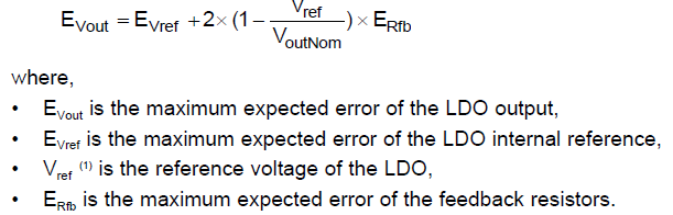
If we apply ANY-OUT version, Erfb = 0, thus Evout = Evref which is 1% of VoutNom accoriding to example in application note.

Let's take VoutNom as 3.3V, Evout (maximum expected error of LDO output) would be 33mV.

According to equation (2):

Let's take IoutMaxSingle = 4A and IoutMaxTotal = 3.5A, Rballast would be 435.6mΩ.

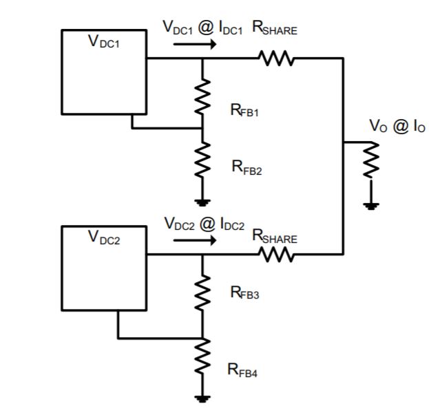
But from what we know, the ballast resistor is used to absorb the output voltage variance between 2 LDOs.

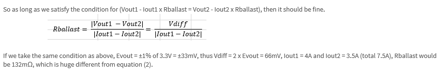
So as long as we satisfy the condition for (Vout1 - Iout1 x Rballast = Vout2 - Iout2 x Rballast), then it should be fine.

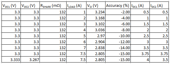
If we take the same condition as above, Evout = ±1% of 3.3V = ±33mV, thus Vdiff = 2 x Evout = 66mV, Iout1 = 4A and Iout2 = 3.5A (total 7.5A), Rballast would be 132mΩ, which is huge different from equation (2).

Can I have the derivation for equation (2)?

Why is VoutNom multiplication apply to equation (2)?

The voltage drop become more significant when the ballast resistor value gets larger.

  • Correction on the IoutMaxTotal, should be 7.5A:

  • Equation is missing from the question:

  • Hi Joe, 

    Thanks for bringing this into our attention. I did the equation myself and found some issues with the equations given in this application note as well. Here are the questions to get Rs (=Rblast). 

    Vo = Vdc1 - Idc1xRs = Vdc2 - Idc2xRs

    so Rs = (Vdc1 - Vdc2) / (Idc1 - Idc2)

    As Idc1 + Idc2 = Iomax, 

    Rs = (Vdc1 - Vdc2) / (2xIdc1 - Iomax). In order to get minimum Rs, Rs needs to have maximum (2xIdc1 - Iomax) = 2xIsingle,max - Iomax

    Because Vdc1 - Vdc2 = Vout-nom x (1+Eout) - Vout-nomx (1+Eout); here Eout = maximum tolerance of output voltage and the unit is in percent. 

    So Vdc1 - Vdc2 = Vout-nom x 2 x Eout ( when one output is at its highest positive Eout and the other is at its lowest negative Eout)

    Then we have Rs = Vout-nom x 2 x Eout / (2xIsingle,max - Iomax). 

    If Isingle,max = 4A, Iomax = 7.5A; Eout = 1%, Vout-nom = 3.3 V; we have Rs = 3.3 x 2 x 1% / (2x4 - 7.5 ) = 132m Ohms. 

    Again, the application note seems to have some problems, I will work on getting it fixed. 

    Regards, 
    Jason Song

  • Hi Jason,

    Your explanation is so clear.

    Thanks!

  • Hi Jason,

    I have further question that you might be able to help.

    Let's take Rs = 132m Ohms.

    It seems that during light load, one of the LDO might need to sink current in order to achieve equilibrium.

    Can TPS7A85 sink current?

  • Hi Joe, 

    Sorry for the late response. LDO as a power device is not meant to take current but at the output pin, the ESD protection may allow certain current to pass through. For the current sharing application, especially at light load, it's hard to achieve the good balance of current load between the LDOs. When LDOs are ramping current load and before the current gets an equilibrium between the LDOs, there could be some smaller voltage difference between outputs. I don't think this smaller difference would damage the LDO if this is what you are concerned about. 

    Regards, 
    Jason Song

  • Hi Jason,

    Thanks for the reply.

    The output voltage drop is so significant at maximum load 7.5A with Rs = 132m ohm, unless I reduce the Rs and maximum current load.

    But then I don't see the purpose to parallel the LDOs if I reduce the maximum current load.

    I think I will just split the power supply into 2 with 2 independent LDOs for better load regulation.

    Thanks anyway.

  • Hi Joe,

    I got you points and I can see the need to reduce the Rblast to a level that will cause less voltage drop especially at higher current. In the TIDA-01232 document, the first paragraph on Page 8, it discusses possible ways to reduce Rshare by measuring the actual Evout. As you can see, based on the test data, Evout can be reduced from 8mV to 0.75mV. If you could also reduce the Evout by 90%, the Rblast value should only be 13mOhms.

    I have noticed one issue with the calculation table you posted, with a combined 7.5A current, you have two Rblast and the current drop through Rblast should be calculated with a maximum current of 4A. 

    You could split the power or using Rblast powering sharing. But obviously, the latter one will require additional optimization to reduce Evout to make the solution practical. 

    Regards,
    Jason

  • Hi Jason,

    Good day to you.

    The Evout = 0.01 x 3.3 = 33mV (1% accuracy for Vout = 3.3V with ANY-OUT configuration).

    If we tie the NR/SS pin together, how much voltage difference between LDOs can further reduce?

    Is there a spec other than taking measurement? Because different sample might have different result?

  • Hi Joe, 

    Unfortunately, there is no specification on the NR/SS for the way that is used to minimize the voltage difference between the two LDOs. Based on the test results of the application note, when connecting two NR/SS together from the two LDOs, the difference can be close to +/- 0.75mV. You may consider using some of the test results from the application note, or you have to run some tests to minimize Evout. 

    "After testing various NR/SS voltages at VoutNom = 0.8 V, the typical range of VOUT for each VNR/SS pin did not surpass 1.5 mV, which would otherwise result in an EVout of ±0.75 mV."

    Regards, 
    Jason