Because of the holidays, TI E2E™ design support forum responses will be delayed from Dec. 25 through Jan. 2. Thank you for your patience.

This thread has been locked.

If you have a related question, please click the "Ask a related question" button in the top right corner. The newly created question will be automatically linked to this question.

BQ2057W: About device operation.

Guru 10745 points

Part Number: BQ2057W

Hi team.

I'd like to tell me about Bq2057 operation.

Our customer designed according to the recommended circuit in the data sheet(p.10).

However, the charging operation does not work.

As a phenomenon, the voltage at the CC pin gradually increases and then becomes the same as the input voltage(VCC/SNS).

But the charging voltage is not fully charged.And then 

A large current flows through to the load when the CC pin voltage is the same as VCC.

Please tell me about bellow questions?

1. Is it correct which The voltage at CC pin gradually increases

   *The increase time is about 5 seconds.

2. Do you have any idea where the problem is that over current flows when the CC pin voltage is the same as VCC?

Sincerely.

Kengo.

  • Hello Kengo

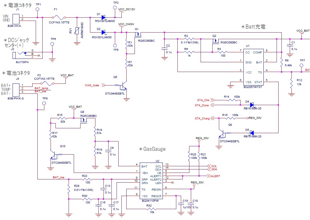
    Do you have a schematic of the circuit with values?

  • Hello Bill.

    Thank you for your reply.

    I'd attached our schematic.

    Please check it.

    If your have any questions in our schematic, please let me know.

    Sincerely.

    Kengo.

  • Hi Kengo

    Thanks for the schematic.

    Q2 may be too small for this application.  The power dissipation in the device will be very high and large device with good heat sink is required.

  • Hi Bill.

    Thank you for your check and reply.

    Is the Bq2057 not working properly because Q2 is small?

    I can not understand our phenomenon what the voltage at the CC pin gradually increases. 

    Does the CC pin behave like a square wave?

    Sincerely.

    Kengo.

  • Hi Kengo

    The BQ2057 is a linear regulator, will behave similar to an LDO regulator with high power dissipation in the pass transistor (Q2).  In your design charge current is set to 1A and even with only a 1V drop across Q2 the power dissipation will be 1W and increase with voltage drop.  

    The evaluation board with a charge current of 500mA will use the larger FZT788B transistor.

    BUT the BQ2057 is a very old device with high external parts count.  The two cell linear charger BQ24004, 005, 006 may be an option.  Also we have a number of switching chargers that will support dual cell applications.

  • Hi Bill.

    My customer changed  FET(Q2) as you said, so it has worked.

    Thank you for your comment.

    And then, my customer looking for FET.

    Do you have a recommend FET?

    Bellow is conditions.

    Vcc : 12V

    Vcharge : 8.4V

    Icharge : 1.3A

    Sincerely.

    Kengo.

  • Hi Kengo

    Thanks for the update.

    The EVM will use FZT788B (BJT) also has the option to use a MOSFET BSP171P.