This thread has been locked.

If you have a related question, please click the "Ask a related question" button in the top right corner. The newly created question will be automatically linked to this question.

TPS43060: Output of VCC-pin

Part Number: TPS43060

Hi support team.


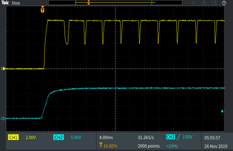
VOUT does not output normally (48V).

The output of VCC-pin does not maintain 7.5V.

CH1: VCC-pin

CH2: VIN 12V


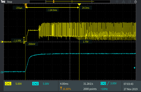
If the capacitor 10uF on the VCC-pin is removed, VOUT (48V) does output.

However, the VCC-pin waveform is further disturbed.


CH1: VCC-pin

CH2: VIN 12V


Is this IC broken?

Please let me know how to normalize the VCC-pin waveform.


Regards,

Dice-K

  • Hi Dice,

    Thank you for using the TPS43060.  Can you show us your schematic for a review, with part values/part numbers accurately labeled?  And, can you tell us your loading conditions when taking the above waveforms?

    Thanks,

    Youhao Xi, Applications Engineering

  • Hi Youhao,

    Thank you for your reply.


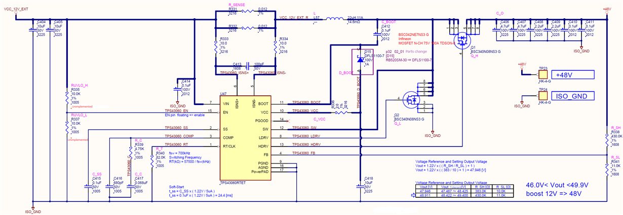
    I attach the schematic.


    The loading current is 520mA.


    Please let me know what should be improved.


    Best regards,

    Dice-K

  • Hi Dice,

    Thank you for posting the schematic.   Do you know what is the parasitic inductance of your current sense resistor?   Let me take a guess and assume it to be about 5nH, then you need to increase C413 to 22nF to get rid of the effects of the the parasitic inductance on the current sense signal, otherwise it can cause false peak current limit.  Please try 22nF and see if there is any improvement.

    Thanks,

    Youhao Xi, Applications Engineering

  • May I assume the issue is resolved and close the thread here?  You are welcome to re-open the thread by adding a new post.

    Thanks,

    Youhao

  • Hi Youhao,

    Thank you for your support.

    Sorry for my late reply.


    Iout = 520mA is when each function on the board is operated at maximum load.

    This event is an operation that cannot output + 48V when the power is turned on, so the current so far does not flow.


    As pointed out by C413 this time, I think that there is a possibility if an erroneous current detection can occur regardless of the amount of current.

    So, the board that sent the waveform last time was broken, so I tried it on another board.

     tps43060_masspro_ng_01_20191211.xlsx

    The board I tried this time was a malfunction in the VCC waveform as shown in the attached AA-column 120-rows.

    This board outputs + 48V at startup, but after operating for a while (the current load has increased somewhat), the +48V output becomes unstable (down to about 20V), and again, The TPS43060 is starting to work.


    Attachment the O-column 120-row is the same as the previous waveform.

    As a precaution, I tried C413 with 22nF on this board, but it did not improve.


    Even if it is caused by incorrect current detection, there is still a question that if I replace the same lot of TPS43060, it will work without any problems.


    After all, when 10uF of C418 is removed, it will operate normally.

    However, the VCC pin waveform is abnormal because there is no capacitor.


    The situation is as above, but is your opinion that current detection is the cause?

    Please give us your opinion.


    Best regards,

    Dice-K

  • Hi Dice-K,

    Thank you for the detailed waveforms.  I did not know this misbehavior only exists to some board. How many pieces of the TPS43060 have such behavior so far?  And how many are okay?  I would like to see if this is related to something damaged in the TPS43060.

    Thanks,

    Youhao

  • Hi Youhao,

    Thank you for your support.


    The number of malfunction is as follows.


                                     Malfunction    Total

    From Market (Digi-Key)         3              130

    From Market (MOUSER)       22             300

    From Distributor                      0                 0


    Digi-Key and MOUSER are different lots.

    Distributor products are not yet used.

    Would you please give me your advice?


    Best regards,

    Dice-K

  • Hi Dice-K,

    We need to further investigate this.  I would discuss with our IC designers. But the following week is holidays, so this may need to wait until after the New Year.  Sorry for any inconvenience this may cause you.  Wish you a happy Holiday Season!

    Thanks,

    Youhao

  • Hi Youhao,

    Thank you for your support.


    Do you have any information updates from IC designers?


    For your reference, I inform you the date code of the IC used by my customer.


    Digi-Key

    ------------

    43060

    TI 8BI

    AV5Q

    ------------


    MOUSER

    ------------

    43060

    TI 86I

    AF96

    ------------


    Please let me know if you need any other information.


    Best regards,

    Dice-K

  • Hi Dice-K,

    I am waiting for our designer who is still on vacation.  Can you confirm one thing:  in previous posts, you mentioned the removal of C418.  Could you place an x7R, 1 to 4.7uF capacitor, anyone but only one in that range?  I am trying to find out if the internal LDO is upset by a larger VCC capacitor.  The datasheet gives an range from 0.47 to 10uF, but a surface value of 10uF may actually have greater capacitance owing to tolerance.

    Thanks,

    Youhao 

  • Hi Youhao,

    Thank you for your support.


    There is no change even if C418 is changed.

    tps43060_masspro_ng_01_20191127.xlsx


    AY Column : No Mounting

    BK Column : 2uF (only +48V output)

    BW Column : 1uF (only +48V output)


    Please give me the opinion of your designer.


    Best regards,

    Dice-K

  • Hi Dice-K,

    Sorry for the delay. The designer is still on vacation. I will try to find other resources to work on this.

    Thanks,

    Youhao

  • Hi Dice-K,

    Again, apology for the delay.  Our design team took a look of the waveforms and they believe the IC was damaged somehow, as VCC should not behave like that. 

    I believe you did ABA test, namely swap the IC with a fresh one on the failing board the circuit can work properly, and installed the failed IC to a new board it also fails, right? If this is true, no insulting but just trying to figure out the cause:  is it possible the IC handling during installation get ESD or some other kind of stress that could damage the IC?   

    Thanks,

    Youhao

  • Hi Youhao,

    Thank you for your support.


    After reporting to the customer, I received the following re-question.


    [Requested question]

    ①From Market (Digi-Key) 3/130 (Malfunction/Total)

    ②From Market (MOUSER) 22/300 (Malfunction/Total)


    After the production / product shipment in , the malfunction was confirmed at the delivery destination.

    In the production process of , we decided to carry out screening before shipping.


    In the inspection process , the following was implemented after component mounting was completed.


    (1) Check for short between each voltage point and GND

    (2) Voltage measurement at each voltage point

    (3) Checking board operation

    ・ In short check and voltage measurement, the points of [VCC_12V_EXT] and [+ 48V] correspond to the area around TPS43060.


    At the product delivery destination, an operation failure occurred after turning on the power to the board several times.

    Therefore, the following (X) step was added to the production process of .


    (1) Check for short between each voltage point and GND

    (X-1) Power ON-OFF once before assembling the module on the board

    (X-2) Power ON-OFF 10 times before measuring voltage

    (2) Voltage measurement at each voltage point

    (3) Checking board operation

    ・ Because there is an LED on the board, if the board is operating at the normal voltage when the power is turned on, we can check whether the LED lights up correctly.

    ・ Power ON-OFF is performed at intervals of ON: 3 seconds or more and OFF: 3 seconds or more.

    ・(X-1) Some sets have been confirmed that the LED lighting is incorrect when the power is turned on for the first time.

       (X-2) After turning on and off 10 times, there is also a case where it is confirmed that the correct voltage is not obtained by the 48V voltage measurement in (2).


     Are there any worrisome points in the above inspection processes (1) and (2) that could lead to IC damage?


    Best regards,

    Dice-K

  • Hi Dice-K,

    Thank you for the info.  We are studying this based on your descriptions. We will get back to you ASAP.

    Thanks,

    Youhao

  • Hi Dice-K,

    Can you short the 2 Ohm resistor between the VCC pin and the VCC capacitor,  namely put a 0 Ohm there, and see if the "bad" board can behave normally?

    Thanks,

    Youhao

  • Hi Youhao,

    Thank you for your support.


    It is a matter of replacing the 2Ω resistor between the VCC pin and the VCC capacitor with 0Ω, but the "bad" board (*1) used for verification has been damaged.

    There seems to be another "bad" board (*2), so the customer will experiment with it.

    It's in a production factory, so customer will experiment as soon as it is available.


    [Symptoms]

    (*1) A device that does not output +48V from power ON and the VCC pin repeats ON / OFF.

    (*2) Output +48V at power ON, but VCC pin keeps dropping to about 4V.

         However, after that, the operation of * 1.


    The customer uses the above (*2) board to conduct experiments.


    Also, I have the following question, can you confirm it?


    [Question]

    Is this the comment of IC designer?

    If we replace the 2Ω resistor between the VCC pin and the VCC capacitor with 0Ω, isn't there a concern that the TPS43060 will break?


    We are worried because the data sheet page-32 "9.2.2.1 Design Requirements" states that a 2Ω resistor should be inserted.


    Other "bad" boards work when the IC is replaced with a good one, so we ship them to the end user if there is no problem.

    Therefore, the number of defective boards is limited.


    Best regards,

    Dice-K

  • Hi Dice-K,

    Thanks.

    Yes, it is the comment from our IC design team. They think the 2 Ohm and the 10uF VCC cap introduces a zero which may upset the VCC regulator.  The test is to verify if the problem is caused by the zero.  In the datasheet, it uses 4.7uF instead of 10uF.  You may also try to reduce the VCC cap to 4.7uF, and it should work with the 2 Ohm resistor.

    Regards,

    Youhao

  • Hi Youhao,

    Thank you for your support.


    The result of the customer test is below.


    [test result]

    Even if the resistance 2 ohm of R336 was changed to 0 ohm, there was no improvemnt.

    (VCC pin keeps dropping to about 4V.)


    Do you have any new counterplans or opinions?


    Best regards,

    Dice-K

  • Hi Dice-K,

    This is strange.  Somehow I lost your schematic (the e2e link seems corrupted).  Can you bother you to resend the schematic, and I will need our design team to take further investigation?

    Thanks

    Youhao

  • Hi Youhao,

    Thank you for your reply


    The schematic is on the previous page.

    Click the "<" to the left below to go to the previous page.


    The customer needs the investigation of your IC design team.


    Best regards,

    Dice-K

  • Thank you Dice-K.   I have asked our design team to take a deeper investigation.  Will update you in a few days.

    Best Regards,

    Youhao

  • Hi Dice-K,

    I invited you for a discussion offline.  Please accept my invitation.

    Thanks,

    Youhao

  • Hi Dice-K,

    Since we are communicating through PMS, let me close this thread here for the time being.  This can be re-opened by adding a new post.

    Thanks,

    Youhao