This thread has been locked.

If you have a related question, please click the "Ask a related question" button in the top right corner. The newly created question will be automatically linked to this question.

TPS650864: TPS6508640

Part Number: TPS650864

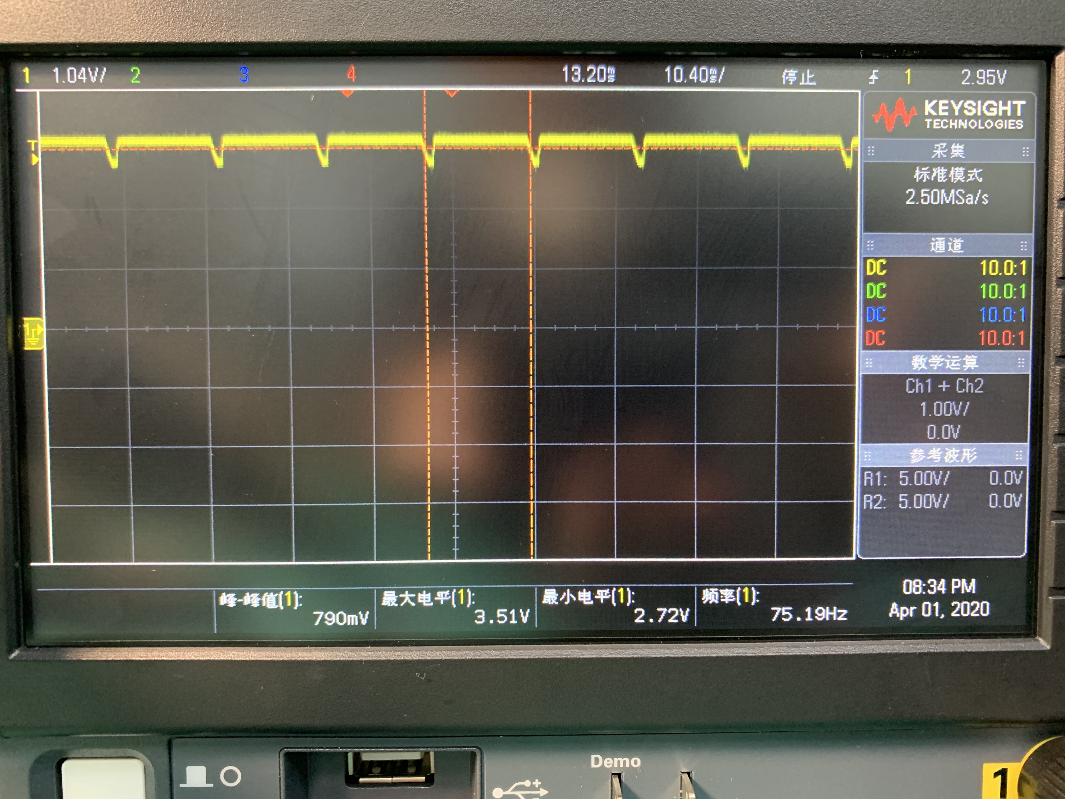
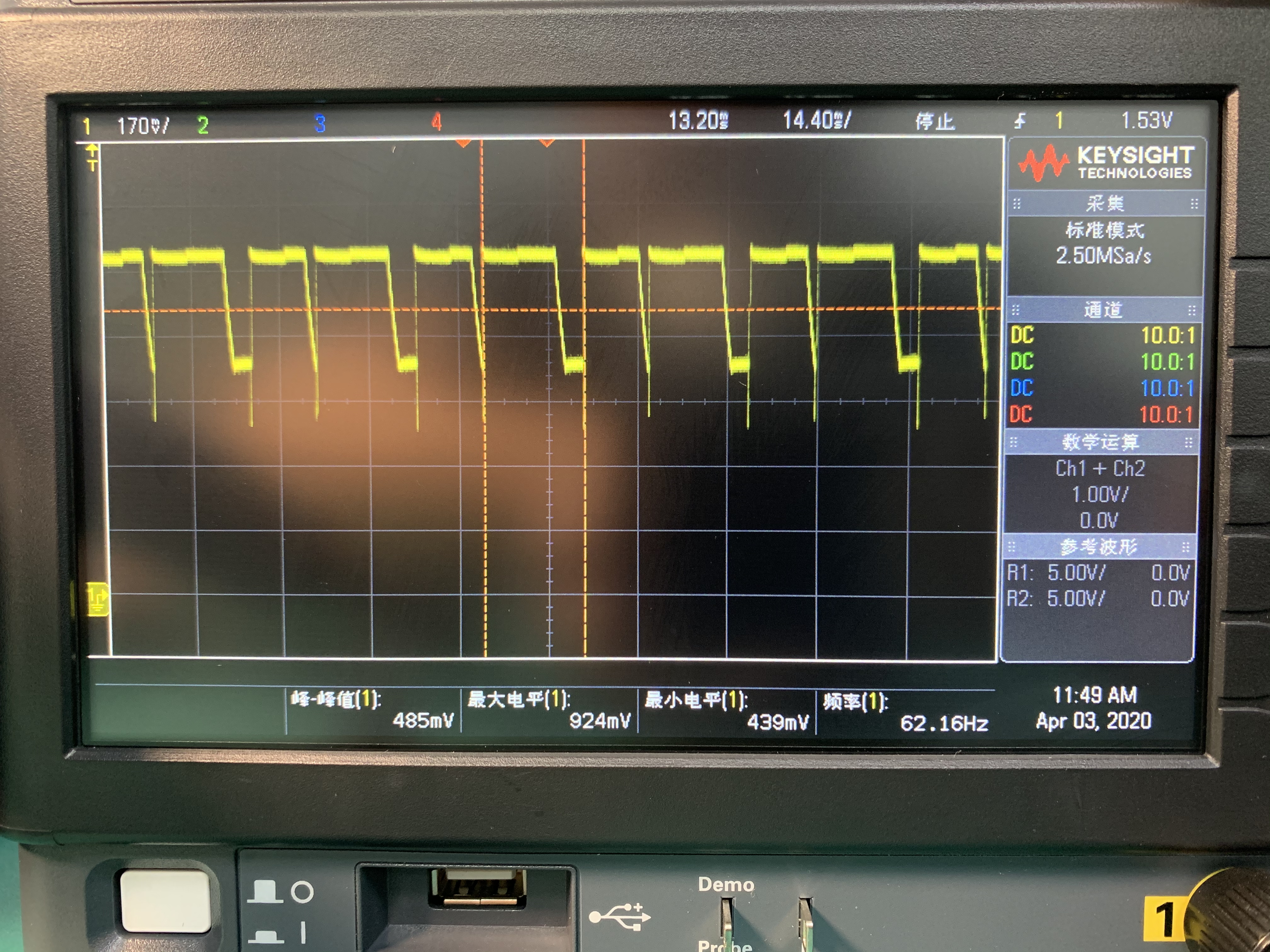
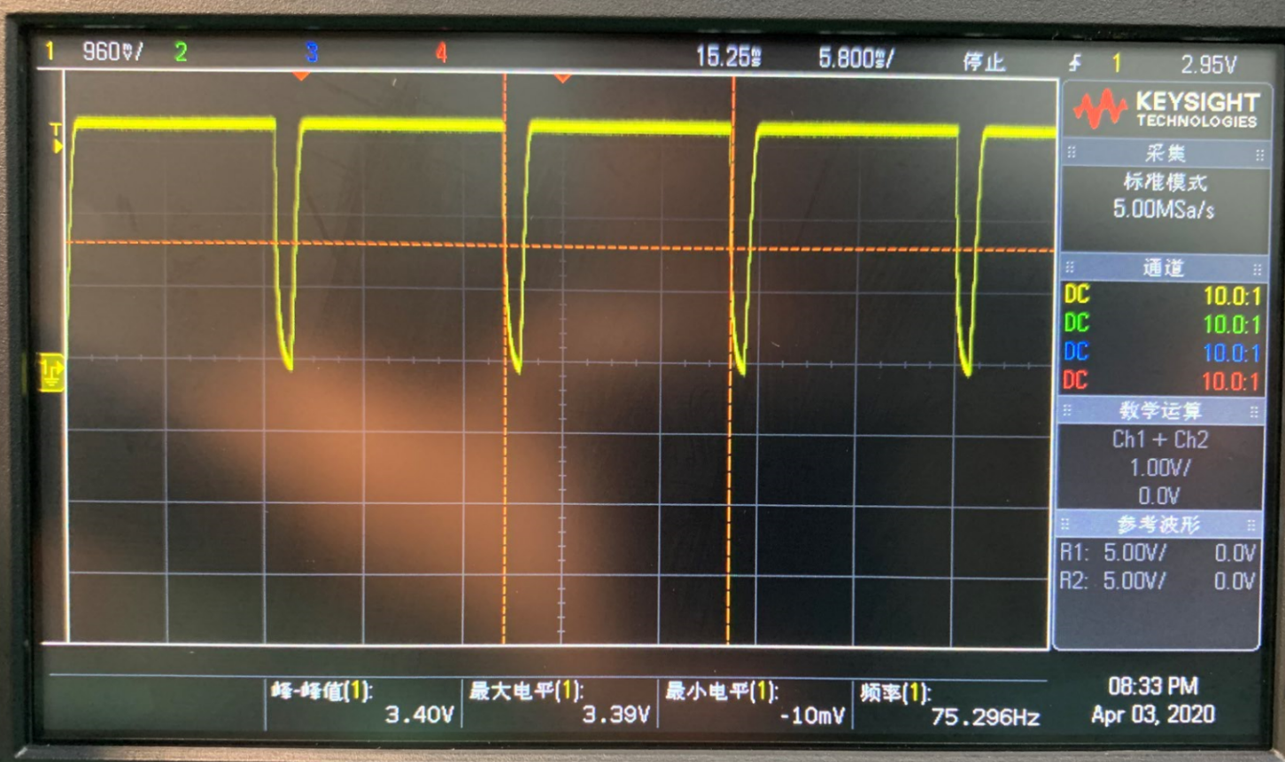
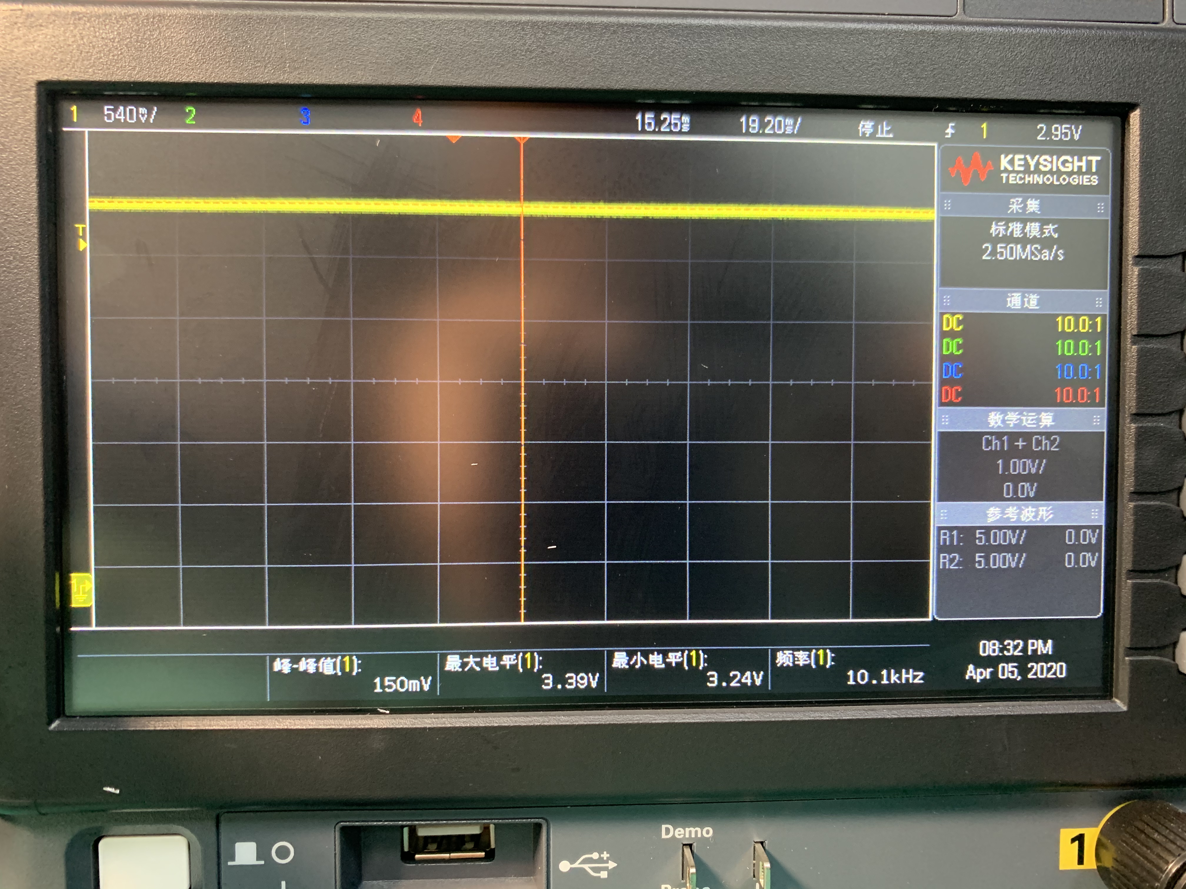
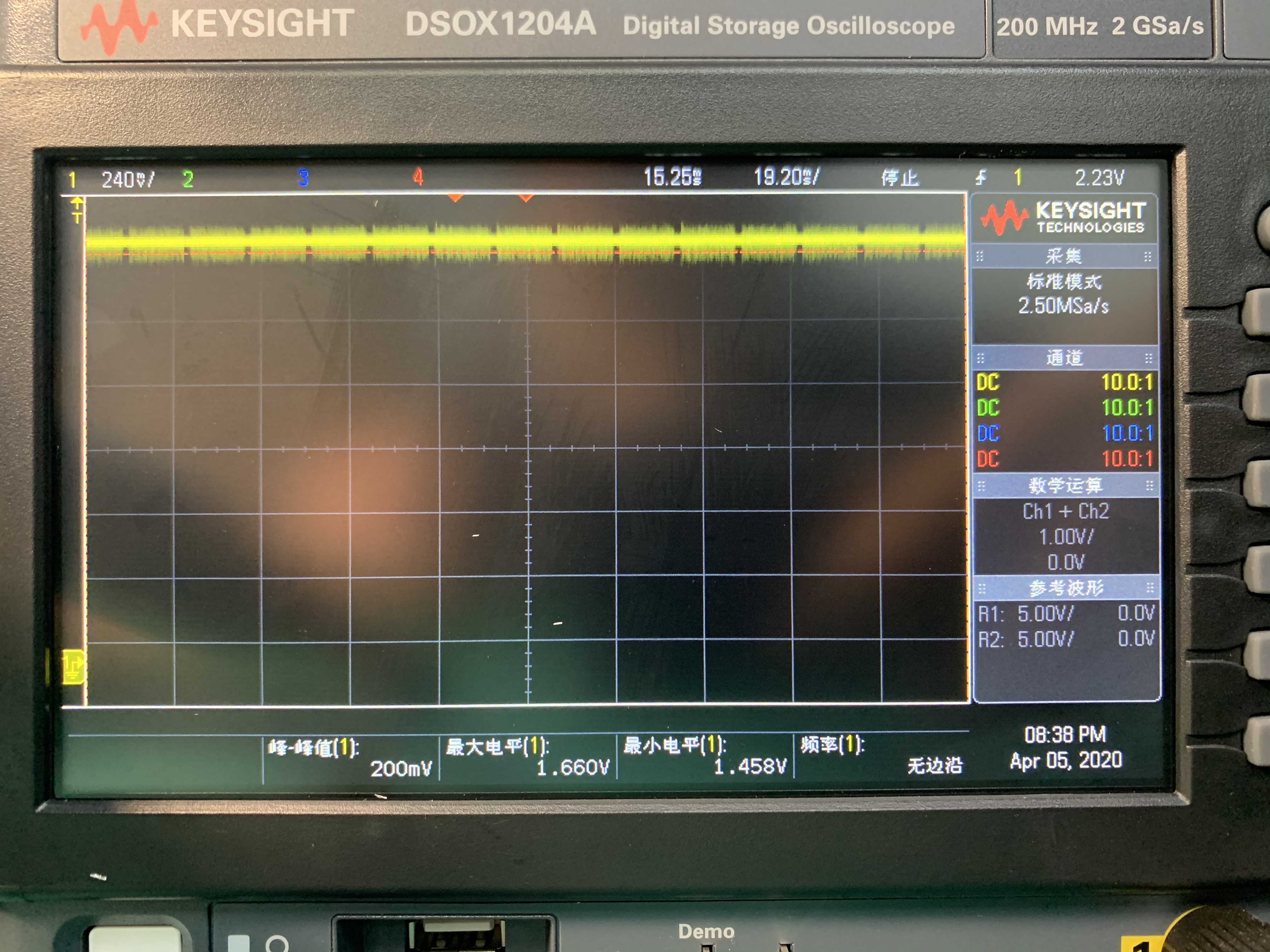
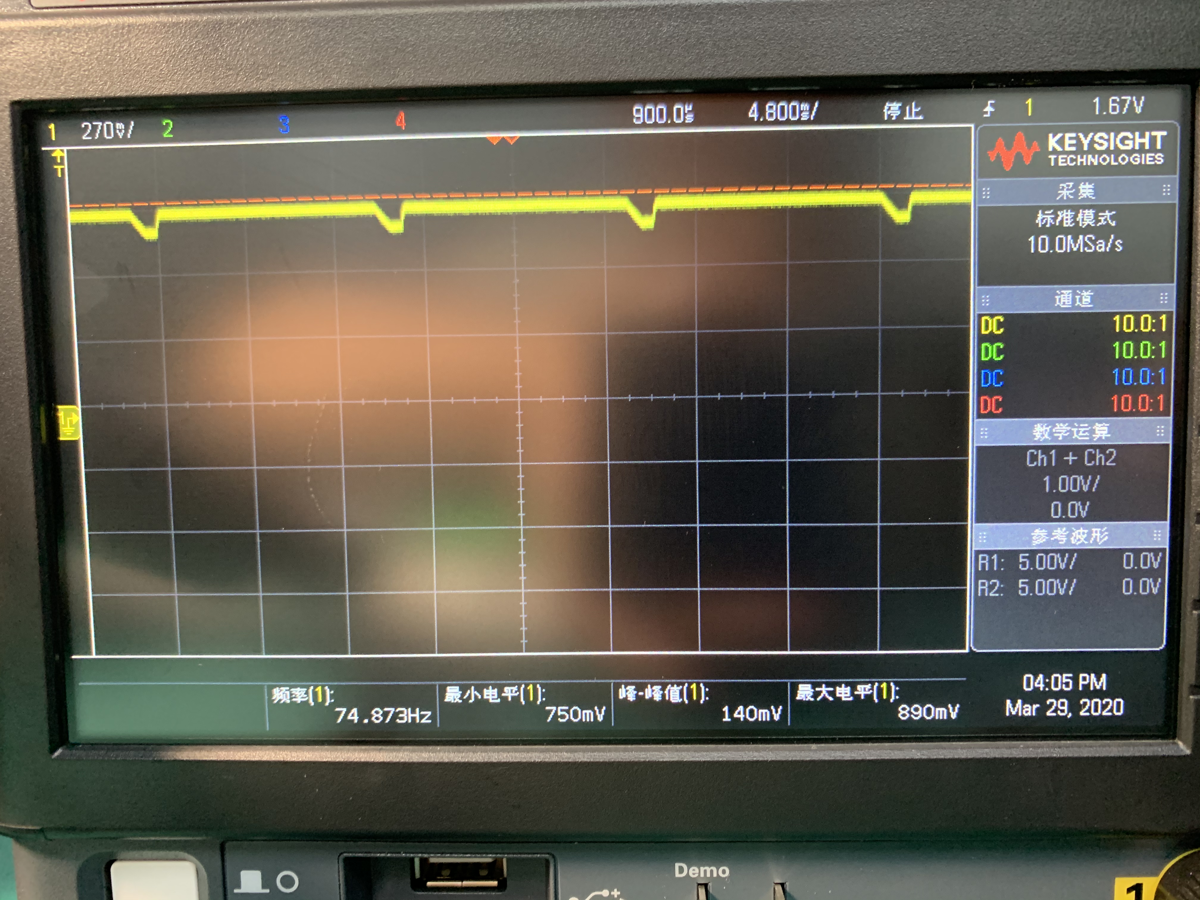
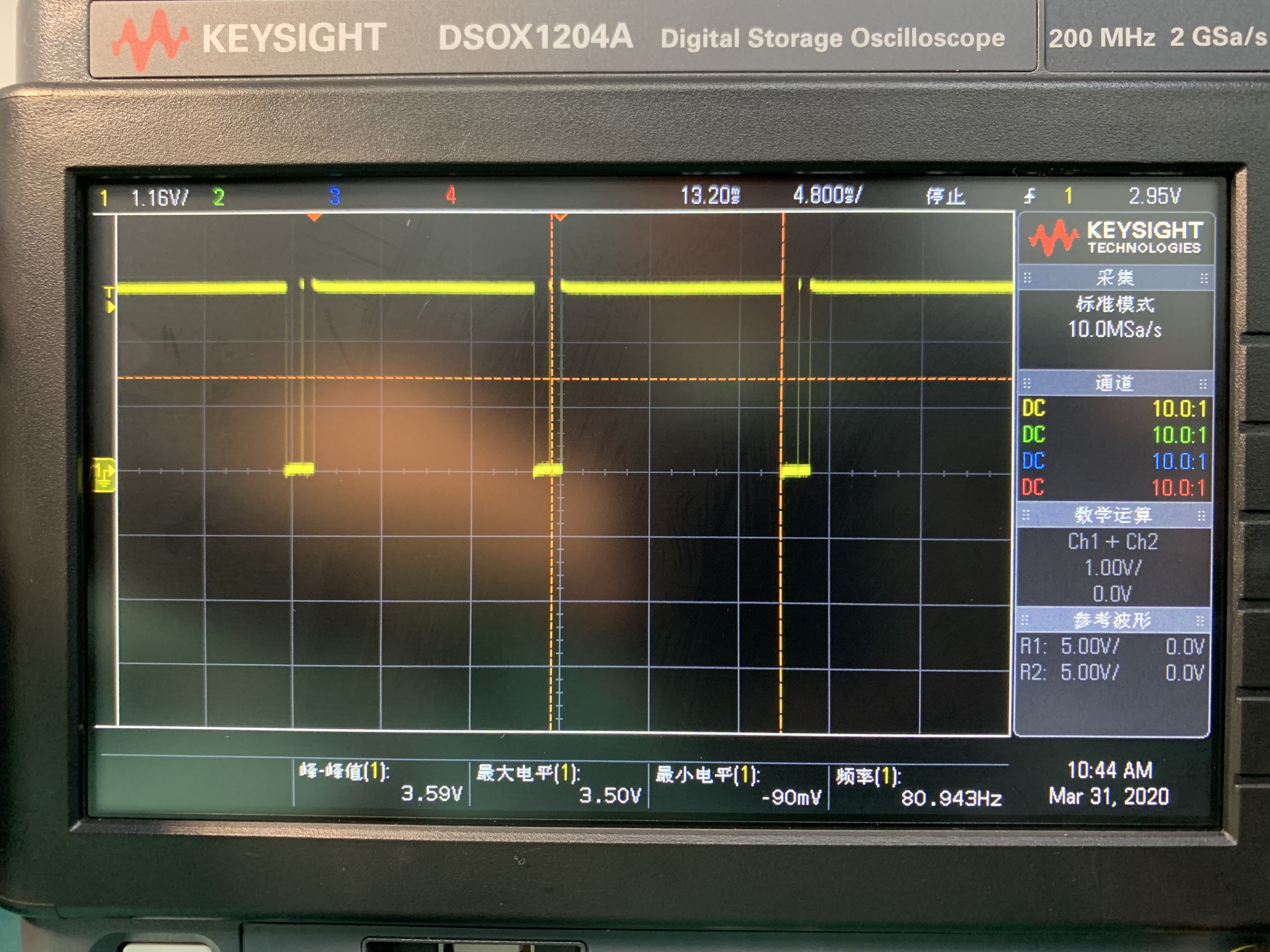
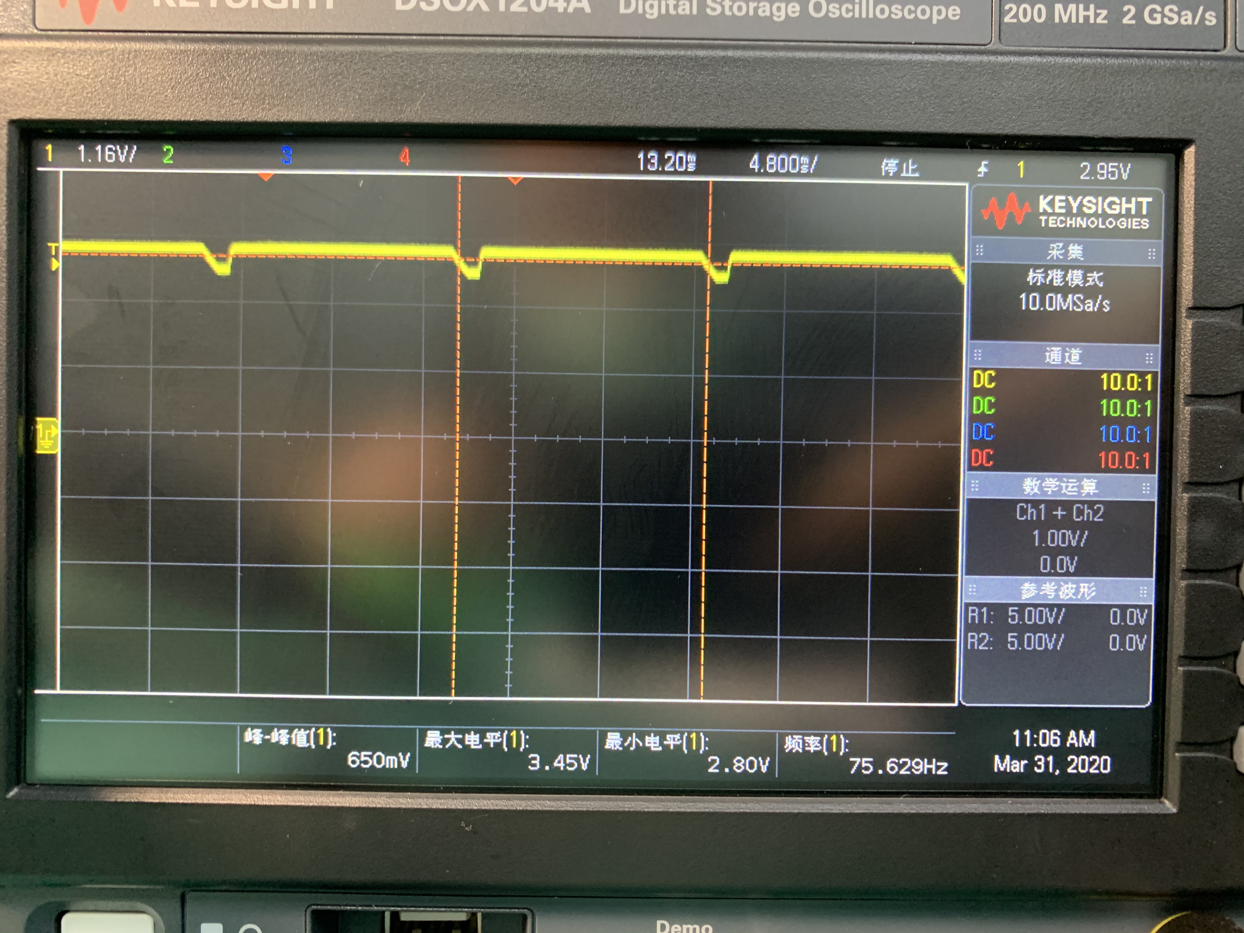
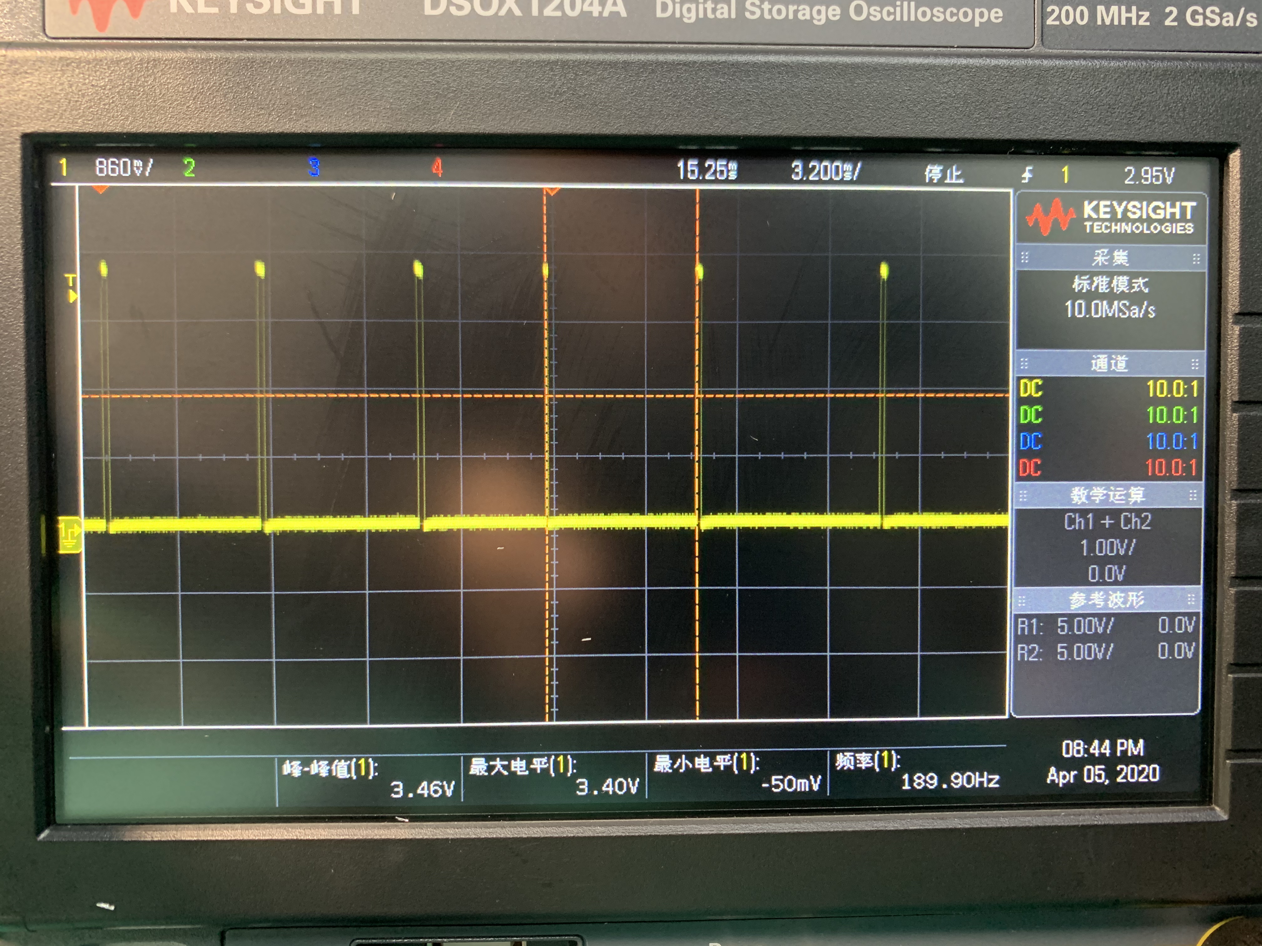
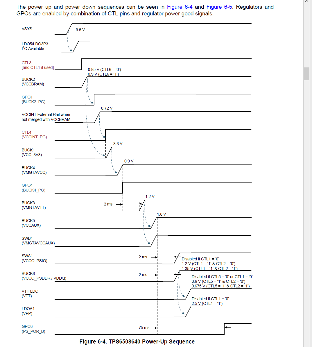
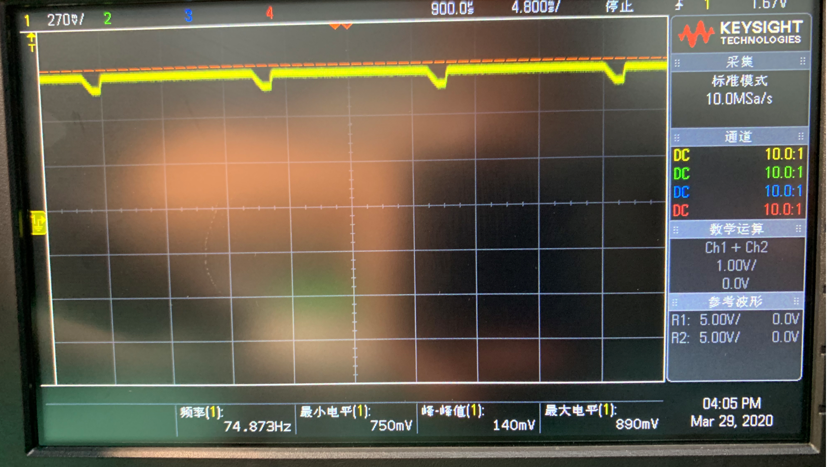
Hello, I designed a board with TPS6508640, with no load at all to test the design. But I can measured a 75 Hz wave in Buck 2 and Buck 1. And there are no output voltage in Buck3\4\5 whos' input are all buck1.

What's wrong with it? Is it because there is no load so there occurs the 75Hz ripple?

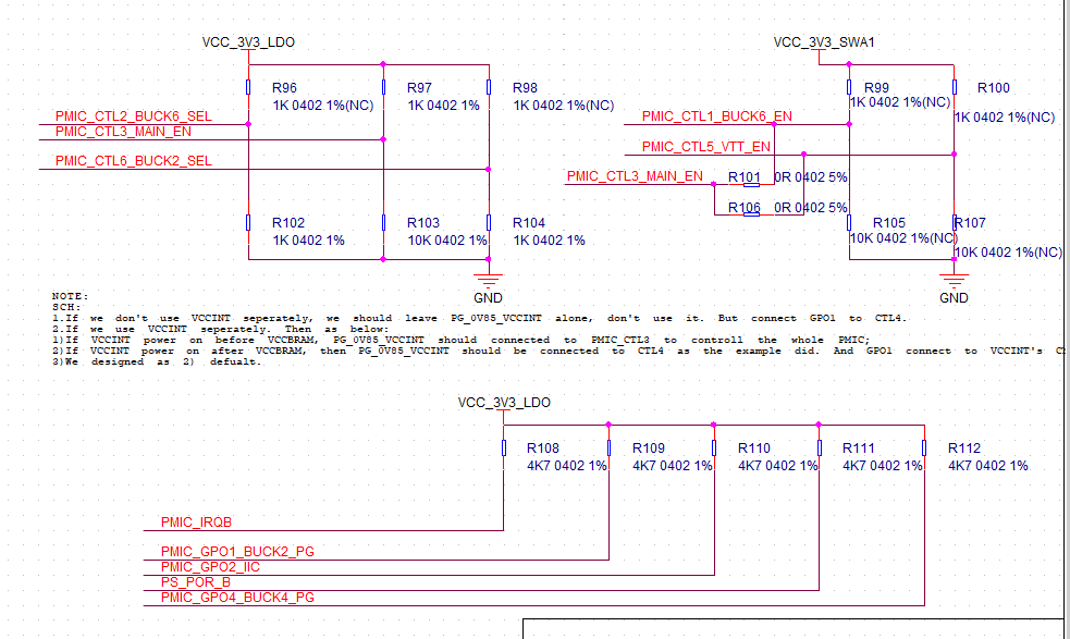
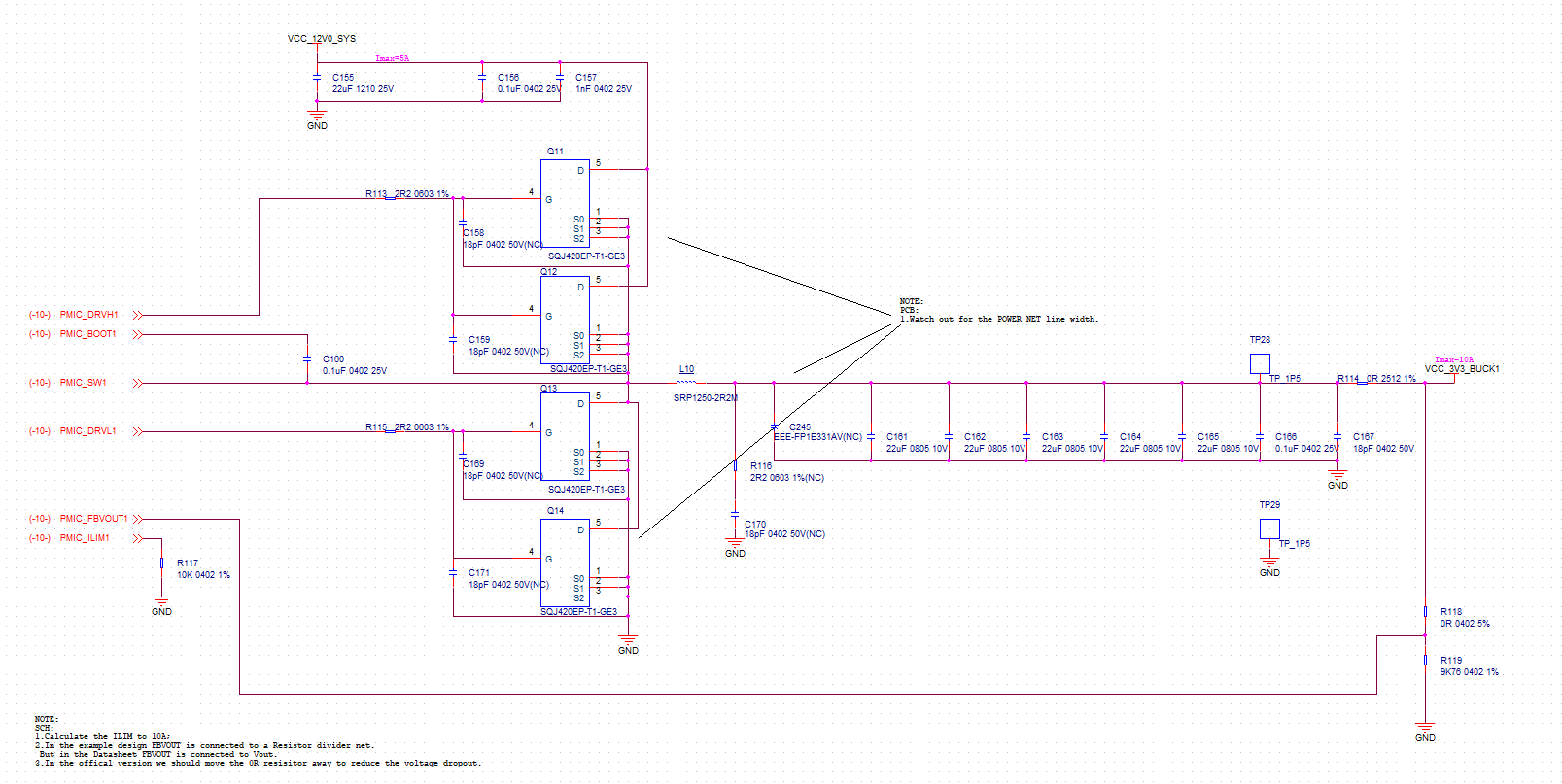
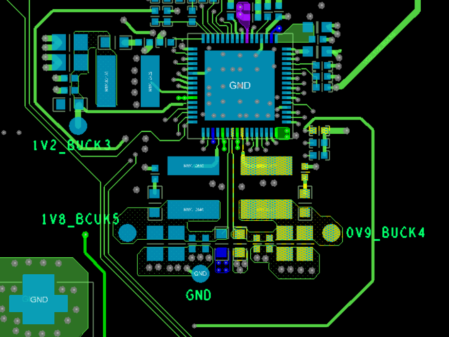
And this is part of my design below.

  • Hi,

    That waveform looks like a power fault. There is a 10 ms mask on power faults, so if any rail of the part is not reaching power good within 10 ms, then the part will shut down.

    I recommend working through Figure 6-4 and figuring out where the sequence is stopping using an oscilloscope. If you get stuck, please post your sequencing oscilloscope shots.

    I started at CTL3, but looking at your schematic image, it looked to me like CTL3 is floating?

  • I pull-up CTL3 to LDO_3V3. It's not floating.  When I disconnect BUCK2_PG with CTL4(which is  BUCK1 EN ), the 75Hz waveform disappear. But if I connect CTL4 to 3V3 to enable BUCK1, the 75Hz waveform appears in BUCK2 and BUCK1.  and BUCK2's PG signal is also 75Hz.   As figure 6-4, BUCK4 output is not right with big ripples. and no output in buck3 and buck5.

  • This is buck1 waveform.

    This is buck4 waveform. 

  • Hello,

    Thank you for confirming CTL3 pullup. Not sure if R103 is intended to be populated, but should have no impact on the PMIC since 3V is still capable of enabling the digital.

    Regarding the waveforms, BUCK4 output certainly looks very abnormal. I looked back at the schematic and realized your inductor is 22 uH, not 220 nH. This converter is expecting 470 nH. Can you switch and see if the performance improves?

    If not, can you post the new scope shot, zoomed in to a single cycle? And please note how much capacitance total is on the output of BUCK4 in addition to the 44uF shown in the schematic as well.

  • Thanks Kevin.

    My inductor is 2.2uH, not 22uH. And I realized the problem so I bought a 470nH inductor to replace it but it is still on it's way. But I think the inductor can't matter much. Big inductor may lead to slighter ripple but worse transient performance.

    I will try the 470nH inductor this afternoon and give your the result.

    Thanks again Kevin.

  • Thanks for the udpate. SRN5040TA-220M shown on the schematic is a 22 uH inductor though, right? https://www.bourns.com/docs/product-datasheets/SRN5040TA.pdf

    I wouldn't have been too worried about stability with a 2.2 uH, but I would expect there to be high risk of loop instability with a 22 uH. 

  • Oh yes sorry, it's 22uH,not 2.2uH. It's my fault. I will try the 470nH as soon as my inductors arrive.

    Thank you very much.

  • I have received my 1uH inductor, and replace the 22uH. Below is the BUCK4 waveform , it's somehow better but still unmormal. 

  • Hi, it looks basically the same as BUCK1 now which is good; it turns on and then there is a power fault on any rail which causes the whole part to shut down.

    I would recommend continuing down the sequence trying to find a rail which does not turn on or turns on to the wrong voltage. Alternatively you could read the power fault registers by I2C to know exactly what the problem is.

  • according to figure 6-4. I did the next few steps  to find out what the problem is:

    1)Disconnected BUCK1's CTL which is BUCK2's PG, and connected BUCK1's CTL to 3v3, BUCK1/2 still had the 75Hz waveform;

    2)Disconnected BUCK1's CTL , and connected BUCK1's CTL to GND, BUCK1 output is 0. and BUCK2 was normal with no 75Hz waveform ;

    3) Disconnected BUCK4's inductor to disable BUCK4, BUCK2/1 still had the 75Hz waveform;

    4)Added a  2ohm resistor load on BUCK1, the 75Hz waveform became more heavy as below.

    5)Change BUCK1's 2.2UH to 470nH , BUCK2/1 still had the 75Hz waveform;

    Here I find maybe the problem is BUCK1. because BUCK1 always has the 75Hz waveform. So the BUCK4\3\5 are all unnormal. Here below is my BUCK3 schemactic, please have a check for me. Thank you.

  • Hi,

    I think I need to repeat a few points because several of these tests suggest a misunderstanding.

    The PMIC will restart if any power rail faults. Meaning if any power rail is enabled and does not reach the expected voltage within 10 ms, the PMIC will turn off all rails.

    When you tested "Disconnected BUCK4's inductor to disable BUCK4, BUCK2/1 still had the 75Hz waveform" - that does not disable BUCK4. That just guarantees the BUCK4 will have a power fault and will guarantee the PMIC resets. So this test did not really test anything. Does that make sense?

    BUCK2, BUCK1, and BUCK4 (with inductor change) look OK. Did you replace the inductors on BUCK3 and BUCK5 too? Otherwise they will probably fail in the same way BUCK4 was. 

    After replacing those inductors, if you do not see the problem fixed, please provide scope shots of the sequencing based on Figure 6-4:

    Scope1: VSYS, LDO3P3, LDO5P0, CTL3

    Scope2: CTL3, BUCK2, GPO1, CTL4

    Scope3: CTL4, BUCK1, BUCK4, GPO4

    Scope4: GPO4 + next 3

    Scope5: + next 3

    Scope6: + next 3

  • BTW Kevin, I found a post in E2E forum below is most likely as my situation.https://e2e.ti.com/support/power-management/f/196/t/881785?tisearch=e2e-sitesearch&keymatch=TPS650864

    So how did him solved the problem finally? I can't read the post wholly.

    And here I add my Schematic as the attachment.sr001_b11_armctrlpwr_t1 200209a.pdf

  • OK, I see , you mean it is the power fault that causes the 75Hz waveform.  I have replaced all the inductors in BUCK4\3\5. Problem still exists. Ok, I will show you the scope shots .

    Scope1: VSYS, LDO3P3, LDO5P0, CTL3

    Scope2: CTL3(above the last one), BUCK2, GPO1, CTL4(the same as GPO1)

    Scope3: CTL4(above), BUCK1, BUCK4, GPO4

    Scope4: GPO4 (above),BUCK3,BUCK5.   The BUCK3 and BUCK5 have no output . Output voltage is 0V.

    FYI. Thank you.

  • Thank you for the additional scope shots. I was expecting them to be in a single scope shot since you have a 4 channel oscilloscope, but I think we can get enough information from this. 

    In particular, the last scope shot has GPO4 being low for the majority of the time. I suspect the points where it goes high are during the OTP re-load disabling the pull down, rather than due to BUCK4 reaching powergood.

    So, I think we can stay focused on BUCK4.

    Looking at the scope shot, I estimate the value of BUCK4 out is 0.875 V instead of the target 0.9 V, but oscilloscopes are not always the best at giving the actual voltage. Can you post the layout of BUCK4?

    I would also recommend replacing the PMIC and seeing if there is an improvement. The 22 uH inductor instability could potentially have damaged the unit.

    You also linked to another post where the layout of BUCK2 controller was creating issues. The BUCK1 controller output voltage image looks very clean, so I don't see that layout being a concern.

  • Hi Kevin. I have gotten another board which never be powerd on and replaced the 3 22uH inductors , but the problem is the same.

    Here is my BUCK4 layout below which is the highlight nets.

    As to another post, my BUCK2 is also pretty pure if I disabble BUCK1. So I think my problem is the same as his.

    And I have given you my Schematic , please check if there is any other problem except the 22uH inductor.

    Thank you.

  • Hi, Kevin:

      I have found the problem , it is because the pin V5ANA . I did not connect it to PIVIN 3\4\5.

    Please lock my post . 

    Thank you. 

  • Thank you for letting me know! Good to hear it is working now.