This thread has been locked.
If you have a related question, please click the "Ask a related question" button in the top right corner. The newly created question will be automatically linked to this question.
I'm considering using a 3v coin cell to power 1.8v components (micro, accelerometer, ADC; 20mA total) but also need a +/-1.5v for the ADC (specifically, ADS1298 to measure ECoG). Low Iq and noise are needed for the 1.5v supply, as it will often be shutdown/disabled. I see one option in the LP5907 for 1.5v:
LP5907 – Low-Iq (12uA); low noise (6.5uVrms); Low dropout (~120mV) (TPS7A20 is slightly better, but not available right now)
For the 1.8v regulation, there are a number of options since noise is not as critical. Low Iq may or may not be an issue, but the TPS7A02 seems to fit the bill:
TPS7A02 – Ultra-low Iq (25nA, 3nA shutdown); higher noise (130uVrms); higher dropout voltage (~400mV)
However, the LP5907 seems to offer better noise and dropout performance at the expense of higher Iq—in the case where Iq isn't a concern, should I just use the LP5907 for both regulators?
Lastly, to generate -1.5v I have used a voltage inverter in the past (MAX1720)—is this the best method/solution? Are there advantages to using a negative-output LDO?
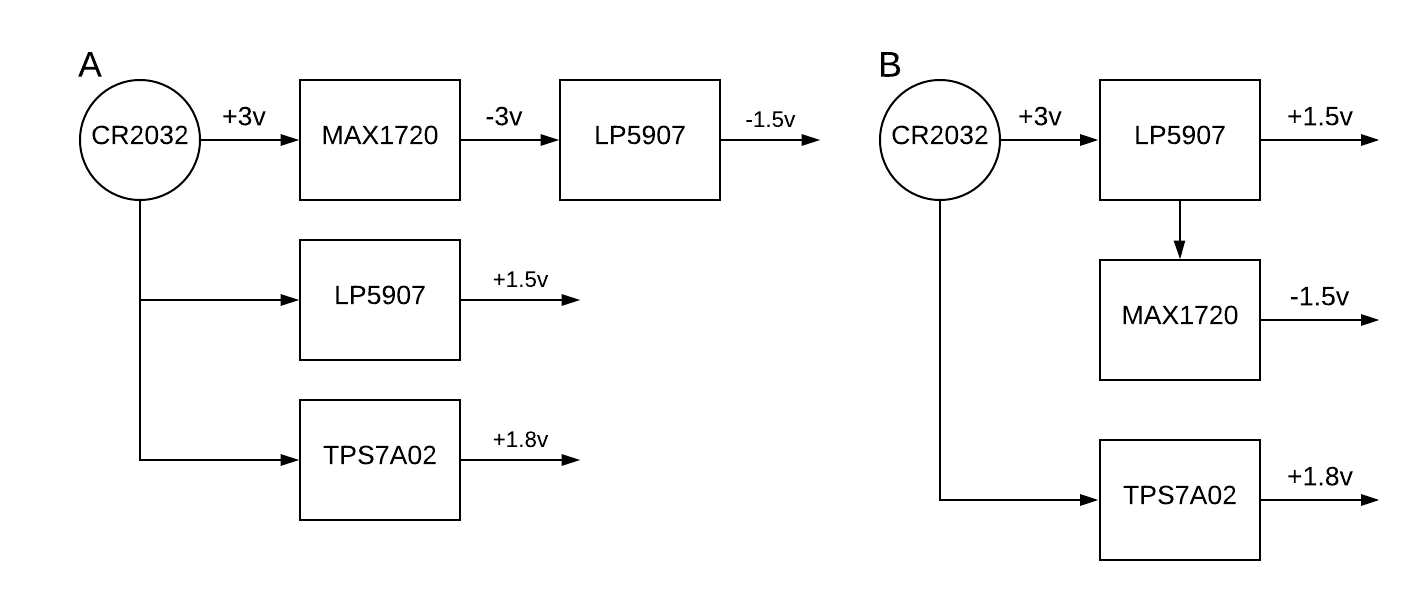
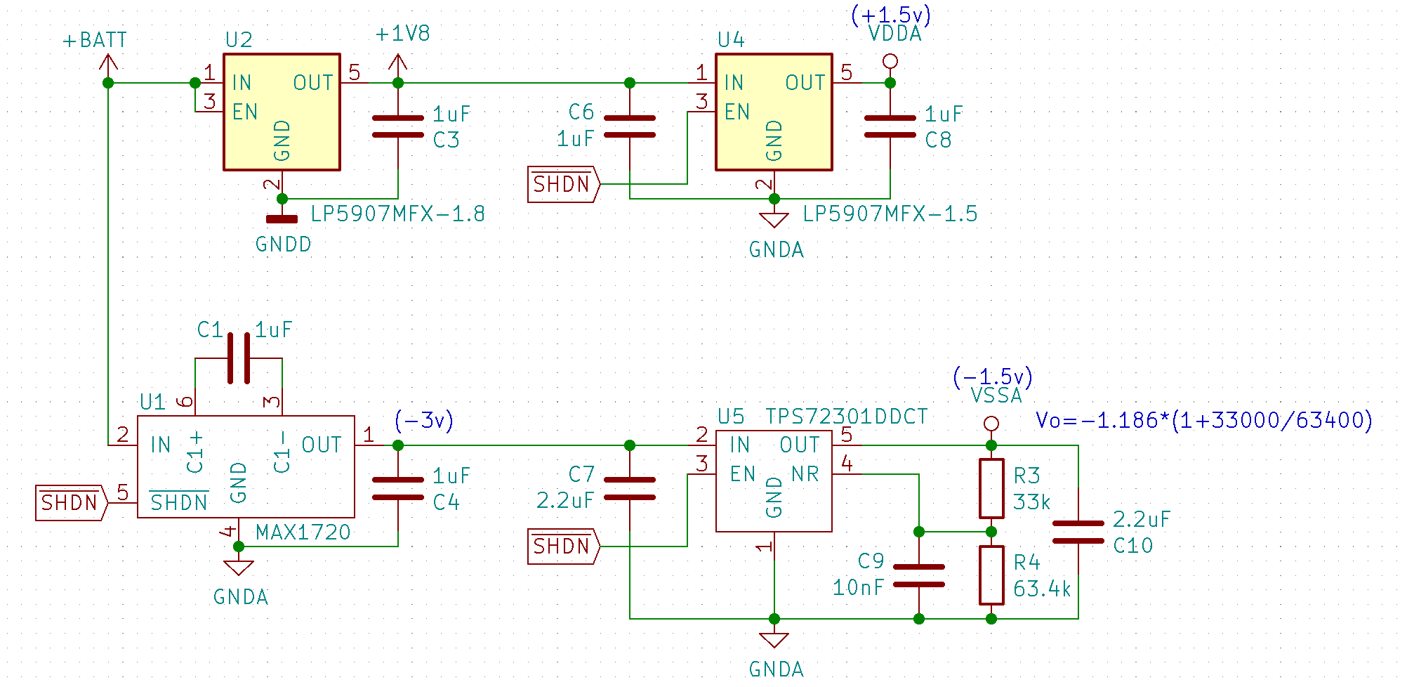
*Note: the ADS1298 dev board where 5v is first inverted to -5v (using TPS6040x) and then makes +2.5 and -2.5 with independent TPS73201 chips (plus a +3v line with TPS73230). Is this design (A) preferred over directly inverting the ADC negative voltage ((B) e.g., +1.8v inverted to -1.8v, design)? The high Iq of the TPS73201 at 0.4mA makes it a poor option for me.
Hi Matt,
I have begun looking into your question and will get back to you tomorrow.
Best regards,
Nick
Hi Matt,
Can you please explain why it is important for the +/-1.5V to be low-Iq but it isn't important for the +1.8V to be low-Iq? If everything is powered by the coin cell then everything should need to be low-Iq, right?
TPS7A02 is a good option for the +1.8V if noise is not as important. Its very low Iq will help conserve a lot of power when not in use.
LP5907 is a good choice if you need low-Iq and also low noise. However, contrary to what is in diagram A, LP5907 cannot be used as a negative Vout LDO. Have you considered using an inverting buck regulator to get the -1.5V?
Matt Gaidica1 said:Lastly, to generate -1.5v I have used a voltage inverter in the past (MAX1720)—is this the best method/solution? Are there advantages to using a negative-output LDO?
There are a number of benefits of using a negative LDO instead of a switched-capacitor inverter. Here are some of the important ones:
I think diagram A is the better architecture, except with the first (top) branch replaced with something else, like a inverting buck regulator.
Best regards,
Nick
Thanks, Nick! My thoughts regarding the +1.8v supply are that it will likely never be shut down since my MCU will either be awake (~5mA) or in some low-power mode (~1mA). However, I'm still working out some details concerning the power-up procedure, in which case low Iq might be beneficial.
I've read that a buck converter is associated with more noise than an LDO. My board design places the ADC extremely close to the power circuitry (~1cm), despite relatively good ground separation: do you believe a buck converter would be compromising in this situation?
If you have part number/s suggestions for the +/- 1.5v supply, that would be great :).
Nick, I'm looking at Minimum power specifications for high-performance ADC power-supply designs and thinking it would be an important point that my ADC is running very slow (250 Hz on the ADS1298). Perhaps the TPS62240DRVT is a good solution to generate 1.8v? (As suggested in Tiny Voltage Regulators Meet Wearable Electronics Space Constraints by Digi-Key).
Hi Matt,
Yes, buck converters have some ripple at the output which is caused by the capacitor at the output discharging to drive the load during the "off" phase. When the load current is small the ripple can be made to be small by choosing the correct inductor value and switching frequency. Here is an app note that describes how to design an efficient switched-mode supply. If you want to go this route (which I think is the most efficient way of getting a negative power rail), you can also use the output of the buck regulator as the input to an LDO to get a nice clean signal with all of the benefits of using an LDO.
As for what parts to use, the TPS723 is a good part for the negative rail and the TPS7A20 or LP5907 for the positive rail.
Hope this helps!
Best regards,
Nick
Nick, great feedback! I feel really confident in this design now. I just want to make sure this is consistent with your reply before I resolve the issue. I'm generating +1.8v from the TPS62243 which feeds into an LP5907 for +1.5v and a TPS723 with an output adjusted to -1.5v. Since my 1.5v rails will only power my ADC, I will use PWM_MODE to force the TPS62243 into fixed-frequency mode while enabling the 1.5v supply chain, while respecting startup time in my software.
This should result in ~6.5uVrms noise on my positive rail and ~60uVrms noise on my negative rail. Also, with PWM_MODE pulled low, Iq is negligible for my application.
Hi Matt,
I think you have a misunderstanding regarding negative output LDOs. Most LDOs that output a negative voltage (with a small number of exceptions) need a negative input voltage as well. You can tell whether this is the case by looking at the range of input voltages in the datasheet. E.g., for TPS723 the recommended input range is min. -10V and max. -2.7V. So, using the +1.8V from the buck regulator as the input will not work with the TPS723. What you should do is use the buck regulator to invert the coin cell voltage and only use that for the TPS723 input. To get the +1.8V you may want to use the LP5907 with the 3V from the coin cell as the input and then you can use another LP5907 to get +1.5V.
Another concern is the dropout voltage for the TPS723. If you used the buck regulator to produce -1.8V, for example, the TPS723 might be in dropout because the max dropout voltage is 500mV and the input voltage is small, which increases the dropout voltage. So since the buck regulator should only be used for the negative power rail, I would recommend configuring it to output a voltage that is sufficiently high that you can be confident the TPS723 will not be in dropout, at least -2V. You can even configure switch-mode supplies to output an inverted voltage of the same value (switch-mode supplies are pretty flexible). The LP5907 is not a concern here because its dropout voltage is max. 250mV (or 200mV depending on the package), so it will not be in dropout with +1.8V in and +1.5V out.
If you're curious about LDOs that can output a positive and negative voltage, check out the LM27762. This could be a nice device to get your +/-1.5 all in one package, but it comes at the cost of a larger quiescent current (~390uA).
I'll keep the thread open so you can post an updated schematic and I'll take a look at it.
Best regards,
Nick
Thanks, Nick, I see my error. I noticed that there are some buck converter products that specifically state the output is negative, whereas Working With Inverting Buck-Boost Converters shows how to invert the signal using any buck converter. Which are you suggesting? I see that the inverting products all have very high Iq, and the LM27762 would be great, but the Iq is also too high.
I am also seeing designs for this ADC using the TPS6040x (charge pump) and LM2664 (switched capacitor) to get the negative supply... I'm thinking that since it is in front on an LDO, perhaps it will be sufficient. The MAX1720 seems to have superior efficiency and the shutdown mode lets me put the entire ADC chain to a low-power mode, whilst removing the inductor and using 0402 capacitors is a major advantage. Here is that design, I suppose one question is whether you see advantages to supplying the LP5907-1.5 directly from +BATT or off the +1.8V line?
Hi Matt,
Sorry for the confusion, I was just trying to give you some more ideas for your design. I've actually never had to design in an inverting buck converter where low Iq is necessary, so I didn't realize that they have such high Iq. So if you wanted to use a buck converter, using a regular converter and configuring it to invert would be the better option.
It is difficult for me to say how this most recent design will work because I haven't used a switched-capacitor inverter as the input to an LDO. My concern is still with the inrush current that happens on startup. Do you have the budget to build a prototype for this part of the power stage to test it before going to layout?
Another related concern you may want to consider is that when the input of an LDO ramps up too slow, there can be overshoot at the output, as discussed in Avoid Start-up Overshoot of LDO.
Matt Gaidica1 said:Here is that design, I suppose one question is whether you see advantages to supplying the LP5907-1.5 directly from +BATT or off the +1.8V line?
I don't see any benefits of using the +BATT voltage as the input to the LP5907-1.5. Reducing Vin for an LDO reduces the power dissipated in the LDO so you would gain that benefit by using the +1.8V as the input and since the dropout voltage for LP5907 is always less than 250mV you don't need to worry about it going into dropout either.
Best regards,
Nick