This thread has been locked.
If you have a related question, please click the "Ask a related question" button in the top right corner. The newly created question will be automatically linked to this question.
DC/DC Switching Converters: Is it possible to run a current-mode converter in voltage-mode only?
If so, is there an example using a buck converter?
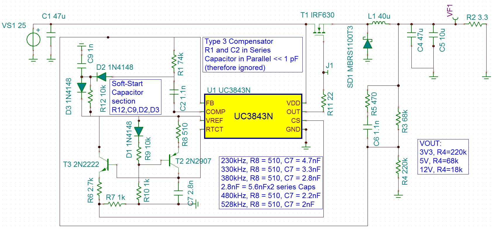
In particular, I'd like to use UC3843 (LT1243) in LTspice as a buck converter in plain-old voltage-mode regulation (disabling current-mode regulation if possible). I've successfully run LT1243 as a SEPIC converter in the past, but I'd like to have run it as a stand-alone buck (step-down) for it's higher efficiency and single winding inductor. I cannot do a flyback (Texas Inst WeBench) for this application.
I've tried grounding the Current Sense (SENSE) pin, or changing the compensation, or changing the load type from a resistor to a fixed current load and it always settles at a particular Vout with respect to Vin, as if Vfeedback has no affect.
The UC384X and LT124X chips are current-mode PWM controller legacy chips.
Datasheet: www.ti.com/.../uc3843.pdf
Thanks in Advance!
Hey Luigi,
Sure, VMC is no problem. Section 8.3.1 from the data sheet you referenced...
Once you treat the current sense as shown in Fig 23 above, the controller is now using the buffered, divided down, RT/CT ramp as the CS - this is VMC. If you're designing a buck stage, then no isolation, direct feedback but make sure you compensate the buck properly. You will most likely be using a Type 3 compensator which is recommended for VMC operating in CCM. SLVA662 here is a good reference for getting you started.
Regards,
Steve M
Steve,
Yes, that is great information in Figure 23, but questions are:
1) Which resistor do I need to set for the frequency RTCT? (Does this still follow the usual RtCt table)?
2) It seems to always converge to Vout of 14V without any affect from VfbTop R3 resistor (that sets output voltage).
Using LT1243 in LTspice, I've implemented Type III 3 compensation using the necessary equations. However, the Resistor (top) and Resistor (bottom) still seem to have no effect on setting the output voltage using feedback resistors. The MOSFET gate is indeed a square wave switching duty cycle does not vary.
Luigi,
1) Which resistor do I need to set for the frequency RTCT? (Does this still follow the usual RtCt table)?
Yes, there may be a slight frequency error (buffered ISENSE signal load on the clock) from what you calculate but follow the usual procedure for frequency setting. RT and CT are R8 and C8 in your LTSPICE model. The RT resistor is shown below as:
2) It seems to always converge to Vout of 14V without any affect from VfbTop R3 resistor (that sets output voltage).
R3 and R2 form a voltage divider from VOUT and this divided down voltage is fed back to the FB pin and compared to the internal 2.5V reference. R2 and R3 are selected according to: VOUT=2.5V*[(R2+R3)/R2]. For your case VOUT=2.5V*[(2k+68.1k)/2k)]=87.6V...this can not happen because a buck demands that VIN>VOUT. Please set R2 and R3 so that you hit your target VOUT regulation and VIN>VOUT.
Also, TI has UC3843, a wide assortment of IC models covering the entire UCx4x family and a free PSICE based simulator, TINA-TI that can be downloaded here. Since you are getting good support from TI, why not make the switch from ADI/LT SPICE?
Regards,
Steve
Steve, thanks for your help. I've successfully run this UC3843 in voltage mode using the setup from the diagram and implementing Type 3 compensation (RC in parallel with RfeedbackTop resistor) in TINA-TI and LTspice. Parameter sweep is great in TINA but I cannot easily obtain efficiencies in it.
As note: Rt must be near 510 Ohms for its ramping oscillator. Any value much greater than or lower than 510 Ohms does not allow the oscillator to work and leaves Ct as the only way to change oscillator frequency.
My questions are:
Thanks !
Steve, thank you for your help here. One final question.
Can voltage-mode be achieved without using transistors NPN/PNP but using diodes instead?
I'd like to not use NPN/PNP transistors, I understand your recommendation, but can this be achieved without transistors but using diodes?
Thank you!
Bipolar transistors have high gain. Given uA of base current, they act as near ideal switches so they are perfect for clock buffering. Diodes are non-linear and even more so at low current. You may get your simulation to run using diodes in place of bipolar transistors but in a real circuit, I believe non-linearity, temperature, process and tolerance variation will be problematic.
Steve M
Steve,
Thank you for fully answering all my questions. I appreciate your feedback!