UCD3138: Multiple interleaved converters and control scheme. Is it possible with multiple UCD3138?

Part Number: UCD3138
Other Parts Discussed in Thread: UCD7138,

Tool/software:

Hi,

Just have seen this topic and I have some questions:  UCD3138: Multiple Interleaved Dual Active Bridge Converters with Phase Shedding 

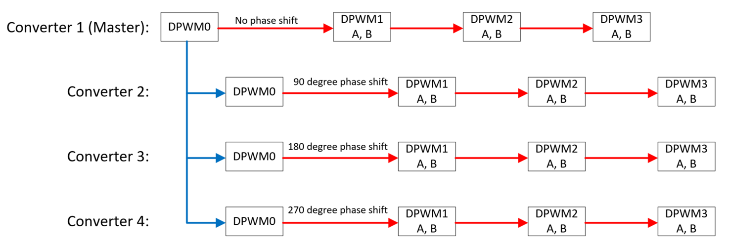
I need to control four different converters with 5pwm each (4 pwm and 1 synchronous rectifier). I need to have a phase shift between all the converters. That is, if Converter A is located at 0°, the next one has to have 90° and so on. A simple representation of this would be:

Converter A PWM 0 (A simple 50% PWM)

|‾‾‾‾‾‾‾‾‾‾‾‾‾|_______|‾‾‾‾‾‾‾‾‾‾‾‾‾|_______|‾‾‾‾‾‾‾‾‾‾‾‾‾|_______

Converter B PWM 0 

‾‾‾‾‾‾|_______|‾‾‾‾‾‾‾‾‾‾‾‾‾|_______|‾‾‾‾‾‾‾‾‾‾‾‾‾|_______|‾‾‾‾‾‾‾

Converter C PWM 0

_______|‾‾‾‾‾‾‾‾‾‾‾‾‾|_______|‾‾‾‾‾‾‾‾‾‾‾‾‾|_______|‾‾‾‾‾‾‾‾‾‾‾‾‾|

Converter D PWM 0

___|‾‾‾‾‾‾‾‾‾‾‾‾‾|_______|‾‾‾‾‾‾‾‾‾‾‾‾‾|_______|‾‾‾‾‾‾‾‾‾‾‾‾‾|____

As it is said in the linked post, it should be possible through communication between different UCD7138. How is this communication done? Are there any application notes?

Another question is for the control loop. I need a PWM signal that does the following:

-Rising edge set to 0. When cycle starts.

-Falling edge set to: The sum of a ramp, a 2p2z transfer function from a measured circuit signal, and a 1p1z transfer function from another measured signal. 

Will this be possible using UCD3138? Is there any documentation regarding sum of multiple transfer function / ramps / arbitrary signals?

Sorry for the inconvenience,

Javier

  • Hi Javier,

    Thank you for providing the required PWM waveform. All the UCD3138 controllers has a SYNC pin which can be used to provide an external signal to synchronize the DPWM outputs of the particular controller. That pin can also be used to generate a signal at the start of period of any particular DPWM of that controller. In this application, one UCD3138 can be used to generate a sync pulse which can be fed to other 3 UCD3138 controllers. You can refer to the following diagram:

    The Blue arrow represents the external connection between the different controllers and the Red arrows represent internal configuration of individual UCD3138 controllers. With this logic, DPWM1 outputs of all of the converters will be phase shifted by 90 degrees from the previous one.

    Please refer to the DPWM and LoopMux chapters in the Technical Reference Manual of UCD3138 for more details: https://www.ti.com/lit/pdf/sniu028

    Regarding your 2nd query, sum of multiple transfer function / ramps / arbitrary signals can be done inside a period interrupt so that the value will be calculated in every cycle. There are 3 digital filters (2p2z) available in each UCD3138. The outputs of those filters can be summed up inside the period interrupt, For more details, please refer to Central Interrupt Module (CIM) section (16.4) in the Technical Reference Manual.

    Regards,

    Soumya