This thread has been locked.

If you have a related question, please click the "Ask a related question" button in the top right corner. The newly created question will be automatically linked to this question.

TPS659037: I am not getting out put from PMIC rails. I have verified 3.3 and 5V at all rails and it is coming correctly. The same design working in older version.

Part Number: TPS659037

This is a new version of AM572X board. In new version i have changed input 12V supply for higher wattage support. No change is done in PMIC section except adding snubber circuit to the  switching node. Previous version of board working perfectly fine.

New version of board i am not seeing output from PMIC rails. Part i have ordered from online vendor, previous built i got from TI. Do i need to tell any specific OTP seeting while ordering these parts.

Below are the part number detail for old and new board.

Part number on new board is TPS659037

                                           OTP 8A 1.3

                                           6CAGXSW G2

                                                            G1

Old board it is TPS659037

                      OTP 8A 1.3

                      6BAZY7W G2

                                       G1

  • Amrendra,

    This question has been assigned to the device expert. We will get back to you soon.

    Jay
  • An update... I am getting output from A8 pin LDOVRTC_OUT as 1.77V only.
  • Hello Amrendra,

    Those two PMICs are the same configuration and part number (OTP 0x8A, PN = TPS6590376ZWSR).  So there should be no difference.

    Do you measure any output voltage with an oscilloscope on the output voltages, eg. SMPS8?  This will tell us if the PMIC is trying to turn on or not.  If it does try to turn on, there may be some issue with the snubber, eg. a short circuit, or too much load.

    If it does not try to turn on, check the ON requests and ON request gating conditions in the State Transition Requests section of the datasheet.  The below conditions need to happen to turn on the device:

    • VCC_SENSE > 3.1V
    • RESET_IN = 1.8V
    • PWRDOWN = 0V (or floating)
    • GPIO_7 = 1.8V OR PWRON = 0V

    I would suggest to check these first, since these are what allow the PMIC to start up.

    Regards,
    Karl

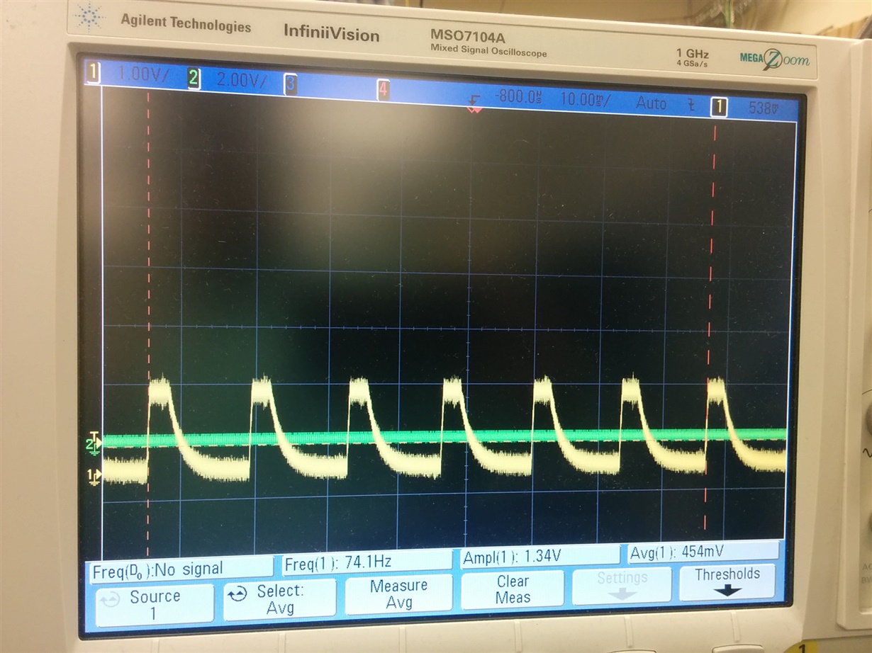
  • Yes i have checked SMPS3, SMPS8 and SMPS4/5. These rails i am seeing a 3.3V waveform with varied duty cycle. So these rails are trying to turn ON. Snubber circuit is DNP(not popultated) on board.

    Attached here is waveform for SMPS8 when load connected.


    VCC_SENSE is 3.35V
    Reset_IN-->1.75V
    PWRDWON is floating
    GPIO_7 -->1.75V

    Thanks
    Amrendra
  • Hi Amrendra,

    I don't see the attachment. Could you double check, and send it again?

    Thanks,
    Karl
  • This is the waveform when load is connected when load is not connected this swing is between 3.3V to 0V and average is 1V.

  • Amrendra,

    It looks like the PMIC is fully powering up, then being switched off. Can you scope the above pins you mentioned (VCC_SENSE, RESET_IN, GPIO_7)? If any of these are toggling after power-up, it makes sense the PMIC will be shutting off.

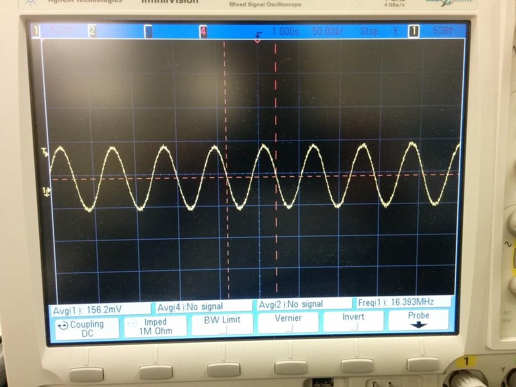
    One other thing to check is the crystal, do you have a 16.384MHz crystal connected to OSC16MIN? If so, please check that the OSC16MIN signal is getting this signal. If the PMIC does not see crystal sine wave at the OSC16MIN pin, some units will issue a reset when it detects too slow clock.

    Regarding the voltage level, I think 1.8V is expected for SMPS8, so that matches your waveform. When you say it is 3.3V without load, is the feedback still connected when you remove the load? SMPS8 voltage could go up to 3.3V if the feedback is not connected.

    Regards,
    Karl

  • Hi Karl

    Attached here is the waveform with  Reset_IN, PWRDN, GPIO7 and SENSE1. I do see a ripple in 3.3V regulator, at 74Hz. I don't think this is an issue for not turning on PMIC.

    I have attached 16.384MHz crystal in my case, Attached is the waveform for this too.

    When load is disconnected feedback also get disconnected. Then i see 3.3V swing. You are correct.

    Thanks

    Amrendra

  • Amrendra,

    Looking at the first waveform, I assume pink / sense1 is the VCC_SENSE pin. I see it dropping to ~2.2V where the trigger is. When VCC drops below 2.75V, it hits VSYS_LO and turns off all outputs immediately. I would check if this is when your outputs are being disabled, and if so try to stabilize the VCC voltage (eg. add capacitance) to prevent reset.

    Regards,
    Karl
  • Hi Karl

    yes the glitch in 3.3V has same frequency as all the switcher on the PMIC. So as soon as switcher tries to turn on the 3.3V goes down.  I have done below experiments to know the root cause.

    1. All loads are disconnected from PMIC, this time there is no feedback to any switcher. Then i get same voltage at inductor as input i.e 3.3V. No glitch on 3.3V. Load switch enables 3.3V to board i.e REGEN1 goes high. Is this a correct observation.

    2. As soon as i try to connect any one switcher of PMIC to load, i start getting  glitch in 3.3V and connected switching nodes have a swing ~2-1.35V and non connected switcher give 3.3V Swing with 74.1Hz.

    3.To know if source 3.3V is issue, i have connected old(working) board 3.3V and 5V to new board 3.3V and 5V. Result is same i.e glitch at 3.3V and PMIC rails doesn't turn ON. Old board PMIC and power supply works fine. So no issue on source side

    4.On output of PMIC i didn't see any short all power rail impedance are correct. I can't disconnect the output with feedback as it is a multilayer board and feedback connected through internal layer.

    Am i missing any pull-up/down settings on PMIC? I didn't see any issue with input/out put rail based on my experiments.

    Thanks

    Amrendra

  • Hi Amrendra,

    If your outputs are going up to 1.15V to 1.8V, then this is the normal output voltage.

    I suggest to measure VCC with each output voltage in the sequence, with ~400us time scale. It could be that VCC drops at the same time one output turns on. I think it's not SMPS8, since the PMIC should shut off ~200us after VCC < 2.75V, and I can see SMPS8 high for ~4ms in your waveform. So you can measure each rail with VCC, and whichever rail turns on at the same time VCC drops, that might indicate where to look for this issue.

    The other thing to check is if RESET_OUT goes high. If so, it means the sequence fully completes, but VCC is dropping after that. When RESET_OUT goes high, this releases the processor out of reset, so this increased load could be causing a dip in VCC.

    Regards,
    Karl
  • Hi Karl

    The issue was due to inrush on load switch. Once the CT capacitor is changed to increase the rise time of 3.3V it resolves the issue of dip in 3.3V and things working fine.

    Thanks for all your support and help.

    Thanks

    Amrendra