Tool/software:
Greetings,
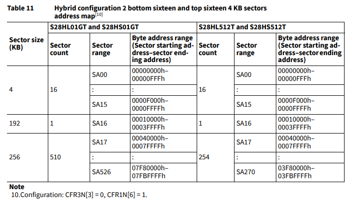
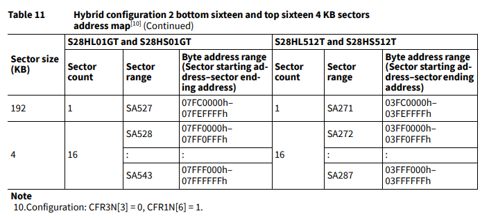
When working with a flash part like S25HL512T or S28HS512T, one will come across Uniform vs Hybrid mode.
The points which this FAQ covers is:
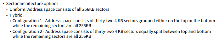
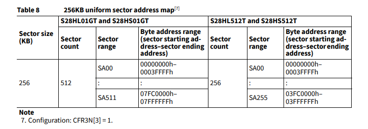
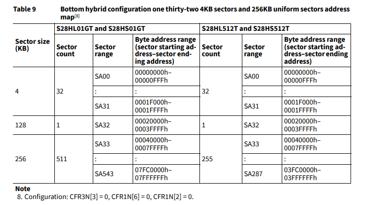
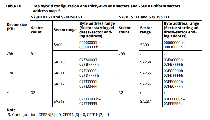
- What is Uniform vs Hybrid Mode for the flash.
- Which mode does MCU PLUS SDK AM6xx Flash drivers work on.
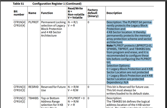
- How to switch from one mode to another.
NOTE: This FAQ applies for AM64x, AM62x, AM243x, AM62Dx
Regards,
Vaibhav