[FAQ] AM625 / AM623 / AM620-Q1 / AM62Ax / AM62Px / AM62D-Q1 / AM62L / AM64x / AM243x Design Recommendations / Custom board hardware design - Queries related to IBIS model

Part Number: AM625
Other Parts Discussed in Thread: AM6442, DS160PR810, AM67

Tool/software:

Hi TI Experts,

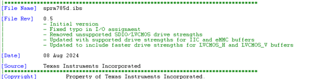
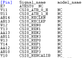
Do you have recommendations on using the IBIS model?

  • Hi Board Designers, 

    Refer below input.

    Q1. Is there a limitation on the number of devices that could be connected to emulated I2C interface given these are LVCMOS IO buffers compared to the Open drain type I2C interface.

    We have customer reusing the current measurement part of the SK 6 INAs, plus 1..2 X EEPROMs + 2 X temp sensors being connected to the emulated I2C interface.

    Answer: The low-level output current (IOL) and output low voltage (VOL) parameters are different for the two ports.  I would not expect any significant functional difference between the these ports with one or two loads.  However, they may observe bigger differences as the number of loads increase.  I’m not able to say how many loads can be connected before it becomes problematic because this depends on the attached devices and the PCB layout.  I recommend they perform a signal quality simulation using the IBIS models of each device along with their actual PCB extractions to confirm the signal levels and signal settling time does not violate any of the I2C specifications.

    Q2. LVCMOS output pin with 1.8VMODE


    The output buffer will source current from the respective VDD IO power rail to the external connections when driven high,
    or sink current from the external connections to VSS when driven low. The signal voltage will depend on the source current or sink current.
    The only data point we define in the datasheet is for current up to 3mA, where the signal voltage will remain less than the max VOL value of 0.45V as
    long as the sink current is less than 3mA, and the signal voltage will remain greater than the min VOH value of (VDD - 0.45V) as long as the source
    current is less than 3mA. The internal voltage dropped across the output buffer will decrease as the current decreases.
    A typical LVCMOS input buffer only has a few uA of input leakage current that needs to be driven by the output buffer to hold a valid logic state.
    There is a good chance external pulls, internal pulls, or combinations of external and internal pulls will present a much larger load than all attached
    input buffers.
    We provide an IBIS model of the output buffer that can be used to determine the resulting signal voltage for operating conditions not defined in the
    datasheet. You will need to create a simulation environment that represents your specific implementation and use the IBIS files of each device to
    determine the steady-state signal voltage for your specific system implementation if you are connecting a device that requires a logic high signal
    voltage that is greater than the min VOH value of (VDD - 0.45V) or a logic low signal voltage that is less than the max VOL value of 0.45V.

    Regards,

    Sreenivasa 

  • Hi Board Designers, 

    IBIS model is showing "NC" for MIPI signals.

    Below is the model used.

    Can u provide an updated model for this Interface with Buffers.

    Did you have a chance to check the AMI model?

    AM62Ax Sitara AMI Model

    The link when downloaded is showing .exe file.

    Do we need to install the app to access the IBIS-AMI?

    Don't we have any readily available IBIS-AMI models for MIPI-CSI 0/1 interfaces. If there is any model available pls do send me.You should be able to double click on the .exe file to install the IBIS-AMI models. This is the only supported option.

    Regards,

    Sreenivasa

  • Hi Board Design,

    FYI.

    (9) DP83867IR: IBIS model verification - Interface forum - Interface - TI E2E support forums

    In the IBIS model for DP83867IRRGZT, pin 15 (X_I) is marked as NC, but the simulation wizard shows Vih as 2 V and Vil as 800 mV, which doesn’t match the 1.8 V logic level I’m using. The same issue is seen in the AM6442 processor, where pin C21 is also marked NC in the IBIS model. I’ve used the latest IBIS models from your website, and changing Vih/Vil values seems to affect undershoot/overshoot in simulations. Could you please clarify this? I will provide the snapshot for your reference.In the IBIS model for DP83867IRRGZT, pin 15 (X_I) is marked as NC, but the simulation wizard shows Vih as 2 V and Vil as 800 mV, which doesn’t match the 1.8 V logic level I’m using. The same issue is seen in the AM6442 processor, where pin C21 is also marked NC in the IBIS model. I’ve used the latest IBIS models from your website, and changing Vih/Vil values seems to affect undershoot/overshoot in simulations. Could you please clarify this? I will provide the snapshot for your reference.
    The Xi input in the IBIS model is NC.Customer is checking the reason for NC.I did E2E search and understand NC is the expected connection. Wanted to get your thoughts.

    Yes NC is expected. This is the oscillator input. We do not provide any IBIS models for this IP.


    I assume the below statement if valid for all the AM62x family of devices?

    Correct
     

    Regards,

    Sreenivasa 

  • Hi Board Designers,

    Inputs related to use case for IBIS and IBIS-AMI simulation models

    Four different IBIS and AMI models are provided for AM62Ax.

    What are the differences between these models? What is each one used for?

    For AM62A, two types of packages, AMB and ANF, are available.

    Are the following two models for the ANF package, and the remaining two models for the AMB package?

    • AM62Ax ANF IBIS Model
    • AM62Ax ANF IBIS-AMI Model

    Is an AMI model for high-speed interfaces?

    • AM62Ax ANF IBIS-AMI Model
    • AM62Ax SitaraTm AMI Model

    Is an IBIS model used for LPDDR4?

    • AM62Ax ANF IBIS Model
    • AM62Ax IBIS Model (Rev. C)

    IBIS-AMI models are used exclusively for simulating high speed (SerDes) interfaces.

    For simulating all other interfaces the IBIS model can be used.

    Models explicitly specified as ANF are for the ANF package while other models are for the AMB package.

    Please note that the recommendation is to use the matching simulation models (for the packages) based on the package selected.

    Additional inputs:

     https://e2e.ti.com/support/interface-group/interface/f/interface-forum/1315498/faq-ds160pr410-difference-between-ibis-ami-versus-ibis-modeling

    IBIS stands for Input/Output Buffering Information Specifications while AMI stands for Algorithm modeling Interface.
    In short, IBIS is used to describe analog behavior of the input or output structure of the buffer or device while IBIS-AMI also
    discusses high speed signal path behavior. Here are some details about each model:

    IBIS-AMI:
    1). Typically comes with DLL and s-parameter files to enable a simulation environment where the user can specify ASIC TX, ASIC RX,
    and transmission media. Using this environment the user can do signal integrity analyses.
    2). S-parameter files can be used to check/study s-parameter behavior across signal frequency of interest.
    3). ASIC TX, RX, and device under test jitter dependent behavior signal integrity can be studied and analyzed.
    4). Allows ASIC and DUT study of equalization on both transmit and receive sides.
    5). Mainly used for giga bit/bits per second high speed signal modeling

    6). Figure below shows IBIS-AMI result using BERT, TL1 s-parameter, DS160PR810 EQ boost model, and ouput eye diagram using real time scope and comparing with IBIS-AMI result:


    IBIS:
    1). Typically it is a single file that allows study of analog buffer on TX and RX sides
    2). ESD structure, output/input buffer, and device package lumped behavior is modeled
    3). Used for low speed less than giga bits per second analog buffer behavior
    4). Mainly used for I vs. V similar to a curve tracer and V vs time

    Regards,

    Sreenivasa

  • Hi Board Designers,

    FYI, IBIS-AMI model support for AM67

    (+) AM67A: IBIS-AMI model request - Processors forum - Processors - TI E2E support forums

    I understand that the IBIS-AMI models are shared under NDA.

    I could confirm customer could use your IBIS-AMI model and they said they did not see any problem.

    Regards,

    Sreenivasa

  • Hi Board Designers,

    Inputs related to IBIS model probe point:

    Could you tell us about the probe point when we simulate with IBIS model?
    Which edge should customer use Die or Pad when at SoC side/Reads?
    (We wonder the the probe point which defined of spec of Reads.)
    DDR4/LPDDR4 read simulations must show margin against the provided eye mask at the SoC DiePad. All other measurements are at the DRAM package pin as defined by the JEDEC spec.
    DDR4/LPDDR4 uses both rising and falling edges of the DQS strobe during reads.
    Refe to AM62x, AM62Lx DDR Board Design and Layout Guidelines www.ti.com/.../sprad06c.pdf
    4.5.3.3 Mask Report
    The minimum jitter and noise margins are to be captured with respect to the eye masks. This masks are data
    rate dependent, and includes:
    • Data read eye mask at the SOC die pad for functionality testing.
    • Data write eye mask (JEDEC spec) at the DRAM pin/BGA for compliance testing.
    • CA bus eye mask (JEDEC spec) at the DRAM pin/BGA for compliance testing.
    Table 4-3. LPDDR4 Eye Mask Definitions/Requirements
    Read eye masks are defined here.

    I was getting eye diagrams that look like the image pasted below. I have since found that it is a lot cleaner when using the die-side probing option in my simulation software. Models from the last interface I simulated did not have a built in package model, so I wasn't aware you could do that.


    It makes sense that die side probing would be what we'd ultimately care about. Let me know if that is not how it is intended to be used though.

    There is no generic guideline that can be given. Different simulations require different points at which the signal needs to be probed and also with different specifications.

    For e.g. the DDR JEDEC specifications for Write transactions require waveforms to be measured at the DRAM BGA, whereas the Read transactions require waveforms to be measured at the SoC Die.

    Regards,

    Sreenivasa