A related question is a question created from another question. When the related question is created, it will be automatically linked to the original question.
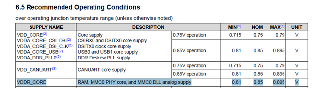
Ther recommendation is to source VDDR_CORE from the same source as VDD_CORE when operating VDD_CORE at 0.85V. I do not see an issue with sourcing VDDR_CORE from a different source as long as they ensure there is no operating condition that allows the potential applied to VDDR_CORE to be greater than the potential applied to VDD_CORE + 0.18V during power-up or power-down. We encourage customers to use the same source for VDDR_CORE and VDD_CORE when operating VDD_CORE at 0.85V to eliminate this concern.
Planned updates to support HS400:
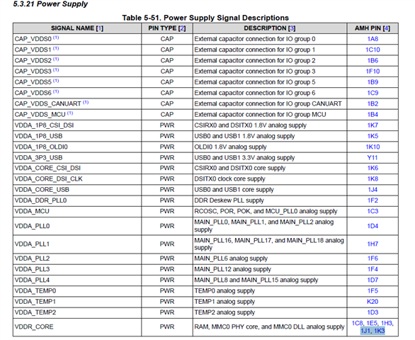
The VDDA_0P85_DLL_MMC0 and VDD_MMC0 power rails, connected to their own pins 1J1 and 1K3 respectively, will be connected to the same net as the VDDR_CORE power rail being sourced from pins 1C8, 1E5, and 1H3. This change combines the VDDR_CORE, VDD_MMC0, and VDDA_0P85_DLL_MMC0 power rails inside the package, where the three power rails will share pins 1C8, 1E5, 1H3, 1J1, and 1K3. I plan to assign the name “VDDR_CORE” to all five pins, and update the signal descriptions to include all three power rails.
This change will create a problem for any customers that is not using MMC0 and they connected the VDDA_0P85_DLL_MMC0 and VDD_MMC0 power rails to the same source as VDD_CORE, as instructed in the previous datasheet. This PCB connectivity will short the 0.75V and 0.85V power supplies together via our new package if they were to install a new package.
The change will also create a problem for systems designed to use two 0.85V power supplies, where one 0.85V power supply is sourcing the VDDA_0P85_DLL_MMC0 and VDD_MMC0 power rails and the other 0.85V power supply is sourcing the VDDR_CORE power rail. This PCB connectivity will short the two 0.85V power supplies together via our new package if they were to install a new package.
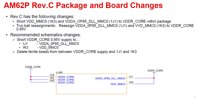
Suggested changes to the schematics
The recommendation is to connect VDDA_0P85_DLL_MMC0 and VDD_MMC0 power rails to the same power source that is connected to VDDR_CORE
Layout Guidelines
The FAQ is being updated. Please review the FAQ for updates.
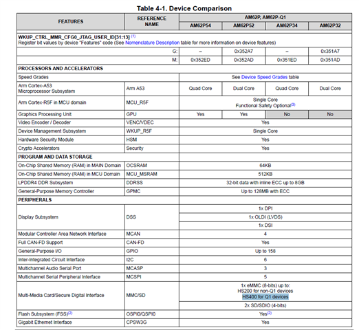
Media and Data Storage: • 3x Multi-Media Card/Secure Digital® (MMC/SD®/ SDIO) interfaces – 1x 8-bit eMMC interface up to: • HS200 for non-Q1 devices • HS400 for Q1 devices – 2x 4-bit SD/SDIO interfaces up to UHS-I – Compliant with eMMC 5.1, SD 3.0, and SDIO Version 3.0
VDDA_0P85_DLL_MMC0 (1J1) and VDD_MMC0 (1K3) power rails are named as VDDR_CORE and connected to the same power source that was sourcing power to VDDR_CORE pins 1C8, 1E5, and 1H3.
The picture above is for understanding the changes.
VDDA_0P85_DLL_MMC0 (1J1) and VDD_MMC0 (1K3) power rails are named as VDDR_CORE and connected to the same power source that was sourcing power to VDDR_CORE pins 1C8, 1E5, and 1H3.