This thread has been locked.

If you have a related question, please click the "Ask a related question" button in the top right corner. The newly created question will be automatically linked to this question.

AM5K2E02: Enabling ECC for DDR3

Part Number: AM5K2E02
Other Parts Discussed in Thread: 66AK2E05

Now we have DDR3 running on our custom board, I need to enable ECC and test that it is working.

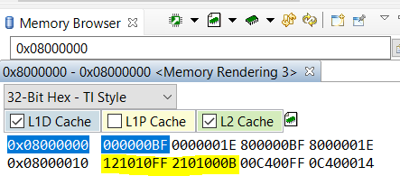
The DDR3 starts at address 0x8000_0000

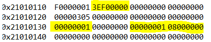
I have tried setting the ECC enable bit in the ECCCTRL register. i.e set value 0x8000_0000 at 0x2101_0110

My test has been to enable ECC, write a word in the DDR3 memory, then disable ECC and change one bit at that location.

I expect that after re-enabling ECC and trying to read the location, it should be corrected and ONE_BIT_ECC_ERR_CNT (0x2101_0130)  incremented.

I have also tried to follow the example ecc_test_app that is provided with the pdk_k2e_4_0_9 distribution to get an interrupt. According to the AM5K2E0x documentation, the DDR3_ERR interrupt is number 388. This doesn't match any of the interrupt numbers in the distribution.

Please can you help me find the correct settings.

thanks

Dan

  • Dan,

    DDR ECC support  in software for this device is only available in software in Linux SDK for this device. The support in PDK for DDR ECC has only been enabled for K2G , AM65x and AM57x devices. The implementation for K2G should be similar to K2E so please refer to the test case provided here:

    pdk_k2g_1_0_15\packages\ti\csl\example\ecc\ecc_test_app (Test for DDR ECC only works from DSP as per release notes)

    You can refer to the DDR init function defined here for enabling DDR ECC in the file pdk_k2g_1_0_15\packages\ti\board\src\evmK2G\evmK2G_ddr.c

    Let me check internally if we have a test for ARM/A15 to check the ECC correction in DDR address range and get back to you.

    Regards,

    Rahul

  • Thanks for responding Rahul,

    There is a similar directory pdk_k2e_4_0_9\packages\ti\csl\example\ecc\ecc_test_app

    I am looking at the differences between
    pdk_k2e_4_0_9\packages\ti\board\src\evmK2G\evmK2G_ddr.c
    pdk_k2e_4_0_9\packages\ti\board\src\evmK2E\evmK2E_ddr.c

    thanks

    Dan

  • Hi Dan,

    "DDR3_ERR interrupt is number 388" this is ARM interrupt for DDR3_A. Unfortunately, we don't have Keystone II device interrupt test example code on ARM under Processor SDK RTOS. We have a plan to do that on K2G but it is not there yet.

    To unblock you:

    One way is you may look at the Processor SDK Linux for K2E, there is DDR test under U-boot.  http://processors.wiki.ti.com/index.php/MCSDK_UG_Chapter_Exploring#DDR3_ECC. Then look at U-boot code how this worked.

    Another way, we have a bare-metal package on Keystone II device created by a former TI engineer, see attached. I looked at it, it has main()------>USIM_config() and USIM_test(). 


    void K2_USIM_Interrupts_Init()
    {
    GIC_INT_Config int_cfg;

    int_cfg.trigger_type= GIC_TRIGGER_TYPE_EDGE;
    int_cfg.ucGroupNum= 1; //route to group 1, IRQ
    int_cfg.ucPriority= GIC400_PRIORITY_LOWEST;

    gpUSIM_regs->IRQSTATUS = 0xFFFFFFFF; //clear interrupt flags
    GIC_interrupt_hook(GIC_CONVERT_SPI_ID(CSL_ARM_GIC_USIM_PONIRQ), &int_cfg, K2_USIM_ISR);
    }

    This is for ARM interrupt #82. 

    Note this package is not maintained and it is not a TI product, and I can only assume it worked some time earlier. This may give you some pointer how to replace the interrupt with #388, as when you introduced the 1-bit ECC error, you should see IRQSTATUS_RAW_SYS set and ONE_BIT_ECC_ERR_CNT increment. Hope this help but we can't support this package.

    Regards, Eric

    https://e2e.ti.com/cfs-file/__key/communityserver-discussions-components-files/791/K2_5F00_STK_5F00_ARM.7z

  • Hi Eric, 

    thanks for the response.

    I have been looking at the various code suggestions including the K2G code base, amd the USIM package that you describe.

    My problem seems to be even more fundamental as I don't even see the error count incrementing.

    my sequence is as follows:

    after setting up the DDR3 mapped at 0x8000_0000,

    I set

    ECCCTL (0x2101_0110) to 0xD000_0001 (ECC _EN | ECC_ADDR_RNG_PROT | RMW_EN | ECC_ADDR_RNG_1_EN)

    ECCADDR1 (0x2101_0114) to 0x1001_1000 (protect region 0x9000_0000 to 0x9001_0000)

    Set a value in the protected region

    *0x9000_0100 = 0xFFFF_FFFF
    *0x9000_0200 = 0xFFFF_FFFF

    Disable ECC by setting
    ECCCTL (0x2101_0110) to 0x4000_0001 (ECC_ADDR_RNG_PROT | ECC_ADDR_RNG_1_EN)

    Change the values in the protected region by one bit

    *0x9000_0100 = 0xEFFF_FFFF
    *0x9000_0200 = 0xFFFF_EFFF

    Re-enable ECC
    ECCCTL (0x2101_0110) to 0xD000_0001 (ECC _EN | ECC_ADDR_RNG_PROT | RMW_EN | ECC_ADDR_RNG_1_EN)

    Read the values written

    test = *0x9000_0100

    test = *0x9000_0200


    I expect that the ONE_BIT_ECC_ERR_CNT should be two after reading the values.

    When I read the value stored at 

    0x2101_0130, it still reads 0x0000_0000.

    What am I doing wrong here?

    I have tried this several times making sure that the cache is disabled (SCTLR bits C, I and Z all set ot 0), and also flushing and invalidating the cache between write and read.

  • Hi,

    "0x2101_0130, it still reads 0x0000_0000." =====>How do you read this address? From A15 or C66x core? Do you use CCS memory window? Is it CPU memory view or Physical Memory View?

    I am trying to say that DDR ECC registers are 36-bit physical address actually. It is 0x1_2101_xxxx. You can read it from 0x2101_xxxx is because you have some mapping setup to translate this. Make sure what you programmed ECCCTL and ECCADDR1 can be viewed correctly, then use the same way to view ONE_BIT_ECC_ERR_CNT register. You also expect to see something log at offset 0x0138 and 0x013C for 1-bit ECC error.

    Also, you programmed ECCADDR1 (0x2101_0114) to 0x1001_1000 (protect region 0x9000_0000 to 0x9001_0000). It doesn't look right for me. You can refer to below https://e2e.ti.com/support/processors/f/791/t/280814. The calculation applies to K2E as well.

    I tested K2H DDR ECC from Linux U-boot before, the same applies to K2E. Below is the register dump after 1-bit ECC ccurred:

      
    The 1-bit ECC is introduced by: http://processors.wiki.ti.com/index.php/MCSDK_UG_Chapter_Exploring#DDR3_ECC

    ddr ecc_err 0x90000000 0x1

    Please update the ECCADDR1 then introduce the error at 0x9000_0000. You should see the same result on K2E use you own code, same as K2H using U-boot.

    Regards, Eric

  • Hi Eric,

    I am getting the same results reading the ONE_BIT_ECC_ERR_CNT  (0x2101_0130) from the CCS memory window and from the code (count = *0x21010130).

    I have looked at the CPU memory 0x2101_0110 and also the physical memory which translates as 0x00_2101_0110. 0x01_2101_0110 shows as unavailable.

    Reading what you have said, I think that the remapping is not correct. It was being set through the MPAX registers in MSMC (0x0bc0_0000) and I am now trying to use the XMC (0x0800_0000).

    Am I looking in the corect area now?

    thanks for your help.

    Dan

  • Dan,

    You need to have something like below (highlighted in yellow).

    Regards, Eric 

  • Hi Eric,

    more strangeness from this end.

    I have been trying to set the XMC MPAX as you suggested, but it always displays as zeroes in the memory browser.

    Ihave been using the folowing sequence to set the register values.

    uint32_t *reg = 0x08000010

    *reg = 0x121010FF

    ++reg

    *reg=0x2101000B

    The memory from 0x0800_0000 is displayed as 0000_0000 in the memory browser window and if I hover over the data, the message "Target failed to read 0x0800_0010" is displayed.

    I looked at the memory map set up in CCS. It is set using the command

    GEL_MapAddStr(0x00000000, 0, 0xFFFFFFFF, "R|W|AS4",0)

    I have tried replacing the access string with "R|W" and with "RAM"

    I have also tried setting up the cache.

    None of these make any difference.

    Incidentlly, I don't see the cache check boxes in the Memory Browser window.

    thanks

    dan

  • Hi,

    You have several issues need to be resolved in order to test K2E ECC interrupt on ARM core.

    1) Make sure DSP C66x (not ARM A15) core 0x0800_0000 region is accessible via JTAG/CCS memory window.

    I just tested on a TI K2E EVM with the standard GEL under ccs_9_0_1\ccs\ccs_base\emulation\boards\evmk2e\gel and there is no issue, you don't have to modify the GEL_MapAddStr. 

    MPAX set up is for DSP core (NOT ARM CORE), that makes you are able to read the EMIF config like below (non-zero) at 0x21010000

    40461C02 40000004 6200CE62 00000000 00001869 00000000 166C9455 00001D4A
    321DFF53 00000000 543F07FF 00000000 00000000 00000000 00000000 00000000
    00000000 00000000 00000000 00000000 00000000 00FFFFFF C0071410 00021C1C
    00002010 00000000 00000000 00000000 00000000 00000000 00000000 00000000
    00000000 00000000 00010000 00000000 F2476311 00000000 00000000 00000000
    00000000 00000000 00000000 00000000 00000000 00000000 00000000 00000000
    00000000 00000000 70073200 00000000 00000000 00000000 00000000 00000000
    00000000 00000000 00000000 00000000 00000000 00000000 00000000 00000000
    00000000 00000000 00000000 00000000 00000000 00000000 00000000 00000000
    00000305 00000000 00000000 00000000 00000000 00000000 00000000 00000000
    00000000 00000000 00000000 00000000 00000000 00000000 00000000 00000000

    I am not sure if any setup in ARM side is needed, I can see the same with address 0x21010000 from A15 without doing anything.

    2) At least you need to make sure this region you can read back correctly either from ARM core or DSP core, so you can see if the 1/2-bit ECC is triggered and logged and if interrupt bit is set

    3) After interrupt bit is set, then you can debug why ARM didn't receive it.

    Regards, Eric 

  • Hi Eric,

    The processor is an AM5K2E02, so there's no DSP core.

    thanks

    dan

  • Dan,

    Even there is no C66x core, I tried TI K2E EVM (it has C66x ) by connecting to A15_0 directly, then look at the address (32-bit address) 0x2101_0000, I can still see the correct value for EMIFCFG.

    All I need is to run the GEL file on A15:  \ccs_9_0_1\ccs\ccs_base\emulation\boards\evmk2e\gel\evmk2e_arm.GEL. You can see that GEL file configures the DDR, it has code like

    #define DDR3A_BASE_ADDR (0x21010000)

    #define DDR3A_STATUS (*(int*)(DDR3A_BASE_ADDR + 0x00000004))
    #define DDR3A_SDCFG (*(int*)(DDR3A_BASE_ADDR + 0x00000008))
    #define DDR3A_SDRFC (*(int*)(DDR3A_BASE_ADDR + 0x00000010))
    #define DDR3A_SDTIM1 (*(int*)(DDR3A_BASE_ADDR + 0x00000018))
    #define DDR3A_SDTIM2 (*(int*)(DDR3A_BASE_ADDR + 0x0000001C))
    #define DDR3A_SDTIM3 (*(int*)(DDR3A_BASE_ADDR + 0x00000020))
    #define DDR3A_SDTIM4 (*(int*)(DDR3A_BASE_ADDR + 0x00000028))
    #define DDR3A_ZQCFG (*(int*)(DDR3A_BASE_ADDR + 0x000000C8))
    #define DDR3A_TMPALRT (*(int*)(DDR3A_BASE_ADDR + 0x000000CC))
    #define DDR3A_DDRPHYC (*(int*)(DDR3A_BASE_ADDR + 0x000000E4))

    And those registers are used by the GEL and run successfully. So there shouldn't be any issue to access the 0x2101_0000 region from CPU/CCS memory window directly using A15 core.

    Regards, Eric

  • Hi Eric,

    this is what is puzzling me.

    I have set up DDR3 using the GEL scripts and run the tests provided by your colleague.

    I then transferred the values determined into C-code and the DDR3 memory was accessible.

    I expected that setting up DDR3 ECC would be straight forward - just a case of setting the enabling bits in the register at 0x2101_0110. I did not initially set the ECCADDR1 or ECCADDR2 values and left those bits unset in ECCCTL. When I was not able to detect any ECC error counts, I implemented them in case this was the issue.

    Is there a GEL script that enables and tests ECC?

    thanks

    dan

  • I have compared the values in the 66AK2E05 datasheet and the AM5K2E0x data sheet and they all look the same I have included the addresses in use in my code too.

    66AK2E05 AM5K2E02 constants value
    DDRA PHY Config 00 0232 9000 00 0232 9FFF 00 0232 9000 00 0232 9FFF C_DDRA_PHY_CONFIG_BASE 0x02329000ul
    DDR3PLL (C_BOOTCFG_DEVICE_STATE_CTRL_BASE+360ul) 0x02620168ul BOOTCFG
    XMC 00 0800 0000 00 0801 FFFF C_XMC_BASE 0x08000000ul
    Multicore shared memory controller (MSMC) config config 00 0BC0 0000 00 0BCF FFFF 00 0BC0 0000 00 0BCF FFFF C_MSMC_BASE 0x0bc00000ul
    MSMC MPAX C_MPAX_BASE 0x0bc00200ul
    DDR3 EMIF Config 00 2101 0000 00 2101 01FF 00 2101 0000 00 2101 01FF C_DDR3_EMIF_CONFIG_BASE; 0x2101000ul
    DDR3 EMIF configuration 01 2100 0000 01 2101 01FF 01 2100 0000 01 2100 01FF

    The DDR3 EMIF configuration is aliased from 01 2100 0000 to 00 2101 0000 in both cases. The 66AK2E05 does not list an offset for XMC.

  • Hi,

    The XMC also exists in 66AK2E05 device. I looked at the data sheet SPRS865B—June 2013—Revised January 2014. It is the same for K2E02 and K2E05.

    If you are able to use GEL to initialize the DDR3, later you also converted the GEL to C code and initialized the DDR3, and DDR3 is accessible. It means the C code works and you should be able to see the EMIF config in the 0x2101_0000 region as non-zero, either from CCS memory window, or use the C code to print those registers from A15. 

    Unfortunately we don't have GEL files to test DDR ECC.

    Regards, Eric

  • Hi Eric,

    I was looking at SPRS865D (2015) which lists that region as reserved:

    00 0800 0000 00 0801 FFFF 128K Reserved Reserved Reserved

    SPRS865B

    00 0800 0000 00 0801 FFFF 128K Extended memory controller (XMC) configuration Extended memory controller (XMC) configuration Extended memory controller (XMC) configuration

    Dan

  • Hi,

    No matter what versions of data sheet, the region of 0x0800_0000 is for the XMC configuration. And I just ran the GEL file on ARM core, ========>Global_Default_Setup_Silent()=======>xmc_setup():

    xmc_setup()
    {
    /* mapping for ddr emif registers XMPAX*2 */

    XMPAX2_L = 0x121010FF; /* replacement addr + perm */
    XMPAX2_H = 0x2101000B; /* base addr + seg size (64KB)*/ //"1B"-->"B" by xj
    GEL_TextOut("XMC setup complete.\n");
    }

    This setup the EMF configuration. 

    It is true that if I looked at the ARM CPU view of 0x0800_0000, it is 0. But if I look at the AM CPU view of 0x2101_0000, it is correct value. 

    So, at least you need to make sure you can duplicate what I saw here: using GEL file running on ARM core 0, you are able to see the EMIF configuration correctly at 0x2101_0000. This is tested on K2E EVM  with 66AK2E05, we don't have EVM with 66AK2E02, but I believe this should be the same behavior.

    Regards, Eric

  • Hi Eric,

    We have five 16-bit DDR3 chips on our board.

    I still can't read the XMC values at 0x0800_0000, but I can read the EMIF values 0x2101_0000. I can configure the DDR3 and the addesses from 0x8000_0000 are accessible.

    Using my version of the evmk2e_arm.gel where I have adjusted the DDR3 parameter values to match our board, I have added some functions to enable the ECC. At the moment there are very basic and should just enable the ECC, write a 64-bit value and then disable the ECC and modify the value before re-enabling and testing.

    The caching is not enabled.

    #define EMIF_ECC_FIFO_BUF_SIZE (0x4U)

    #define EMIF_START_ADDR (0x80000000)
    #define EMIF_ECC_START_ADDR (0x90000000)
    #define EMIF_ECC_END_ADDR (0x9003FFFF)

    #define EMIF_ECC_1B_ERR_THRSH_VAL (0x2)

    #define DDR3A_BASE  (0x21010000)

    #define DDR3A_ECCCTL *(unsigned int *)(DDR3A_BASE+0x00000110)
    #define ECC_ADDR_RNG1_EN (0x00000001)
    #define ECC_ADDR_RNG2_EN (0x00000002)
    #define ECC_RMW_EN (0x10000000)
    #define ECC_VERIFY_EN (0x20000000)
    #define ECC_ADDR_RNG_PROT_EN (0x40000000)
    #define ECC_EN (0x80000000)

    #define DDR3A_ADDR1 *(unsigned int *)(DDR3A_BASE+0x00000114)
    #define DDR3A_ADDR2 *(unsigned int *)(DDR3A_BASE+0x00000118)

    #define DDR3A_ECC_1B_CNT *(unsigned int *)(DDR3A_BASE+0x00000130)
    menuitem "Test ECC "

    ECC_InitRange()
    {
    GEL_TextOut( "Setting Range for ECC\n");
    }

    ECCConfig(uint32_t value)
    {

    GEL_TextOut( "Configure ECC\n");
    }

    DisableECC()
    {
    GEL_TextOut( "Disable ECC\n");
    DDR3A_ECCCTL &= ~ECC_EN;
    GEL_TextOut("ECCCTL = %x\n",,,,, DDR3A_ECCCTL);
    }

    EnableECC()
    {
    GEL_TextOut( "Enable ECC\n");
    DDR3A_ECCCTL |= ECC_EN;
    GEL_TextOut("ECCCTL = %x\n",,,,, DDR3A_ECCCTL);
    }

    ResetData()
    {
    GEL_TextOut( "Reset Data\n");
    }

    Get1BCount()
    {
    unsigned int cnt;
    cnt = DDR3A_ECC_1B_CNT;
    GEL_TextOut(" One BitCount = %d\n",,,,, cnt);

    }

    hotmenu InitECC()
    {
    GEL_TextOut( "Initialising ECC\n");
    ECC_InitRange();
    ResetData();
    EnableECC();
    }

    hotmenu testECC()
    {

    GEL_TextOut( "Testing ECC\n");
    EnableECC();

    *(unsigned long long int *)EMIF_ECC_START_ADDR = 0xfedcba9876543211;
    Get1BCount();

    DisableECC();

    *(unsigned long long int *)EMIF_ECC_START_ADDR = 0xfedcba9876543210;

    EnableECC();
    GEL_TextOut( "Reading %x %x\n",,,,, EMIF_ECC_START_ADDR, *(unsigned long long int *)EMIF_ECC_START_ADDR);
    Get1BCount();

    }

    thanks

    dan

  • Dan,

    I thought you have some code we pointed out earlier to follow, e.g., the test code for K2G under pdk_k2g_1_0_15\packages\ti\csl\example\ecc\ecc_test_app. This should work for K2E as well. You converted the same to GEL. If you introduce a 1-bit error, do you see that it reflected on DDR ECC interrupt status and error statistics registers (e.g. offset 0xa4, 0xac, 0xb4, 0xbc, 0x130, 0x138, 0x13c). If no, you need to check why? If yes, then the next step is how to hook A15 interrupt. 

    Regards, Eric

  • Hi Eric,

    Yes, I am now seeing changes in the error registers when I introduce 1 bit error.

    I have now been transferring the GEL files back into C in my application and am getting the interrupts working. At the moment the interrupt is being generated but not being handled correctly in the IRQ.

    thanks for your patience.

    Dan

  • Hi Eric,

    I think that I am finally getting to the last piece of the puzzle.

    In my test code, I set up ECC with the following parameters:

    DDR3 starts at 0x8000_0000

    ECCCTL (0x2101_0110) 0xF000_0001

    ECCADDR1 (0x2101_0114) 0x08010800 protecting 0x9000_0000 - 0x9003_FFFF

    I clear all the ECC error values

    ONE_BIT_ECC_ERR_CNT (0x2101_0130)

    ONE_BIT_ECC_ERR_DST_1 (0x2101_0138)

    ONE_BIT_ECC_ERR_ADDR_LOG_1 (0x2101_013C)

    TWO_BIT_ECC_ERR_ADDR_LOG_1 (0x2101_0140)

    ONE_BIT_ECC_ERR_DST_2 (0x2101_0144)

    I enable the interrupts by setting 

    IRQENABLE_SET_SYS (0x2101_00B4)  0x0000_0038

    IRQENABLE_CLR_SYS (0x2101_00BC)  0x0000_0038

    the 64-bit word in DDR3 at 0x9000_0100 to 0xFFFF_FFFF_FFFF_FFFF with ECC enabled.

    I disable ECC (set 0x2101_0110 to 0x7000_0001)

    Set the value at 0x9000_0100 to 0xFFFF_FFFF_FFFF_FFFE

    Then when I re-enable ECC and read the test value, the following error values are set:

    ONE_BIT_ECC_ERR_CNT (0x2101_0130) 0x0000_0008 (typically, but I expect that this should be 1)

    ONE_BIT_ECC_ERR_DST_1 (0x2101_0138) 0x0000_0001 (this is expected)

    ONE_BIT_ECC_ERR_ADDR_LOG_1 (0x2101_013C) 0x0800_0080 (I think that this translates to 0x9000_0100 which is expected)

    ONE_BIT_ECC_ERR_DST_2 (0x2101_0144) 0x0000_0201 (I expect that this should be 0)

    TWO_BIT_ECC_ERR_ADDR_LOG_1 (0x2101_0140) is usually 0, but sometimes is 0x0800_0080.

    I don't understand why I am getting multiple single-bit errors, and why I get a double-bit error.

    The double-bit error always seems to generate a data-abort exception. Is this normal? Is there a way of preventing this for test purposes?

    thanks

    dan

  • Dan,

    Your current test is in A15 or C66x? And both saw the same issue? Most of the register values made sense. But it is strange for error distribution on high bit lanes and two-bit address log. I tested 1-bit error (in the beginning of the thread) of K2H and didn't find such issue using U-boot. The K2H and K2E are the same DDR3 controller, so expect the same results. Are you able to write the U-boot to the flash, do the 1-bit ECC test, then connect the JTAG to look at those EMIF registers.

    If you test a few times and always got the consistent and expected results, then you may look at the U-boot code to see if the ECCCTL different and test sequence different.

    For the data-abort exception, In  IRQENABLE_SET_SYS, if you set this to 0x28 (e.g, disable 2-bit ECC error interrupt), will this help?

    Regards, Eric

  • Hi Eric,

    I tried setting the IRQENABLE_SET_SYS to 0x28, but that means that the data-abort exception is still raised, but without the 2-bit ECC interrupt firing.

    I have done some more tests and with ECC enabled I get the two bit error even when I write the value in the protected region and read it back immediately.

    I suspect that the ECC bits are not being set correctly.

    I will investigate this next year as I will be off until 2nd January.

    Thanks for your help.

    Happy holidays

    dan

  • Dan,

    Happy Holidays!

    Regards, Eric