This thread has been locked.

If you have a related question, please click the "Ask a related question" button in the top right corner. The newly created question will be automatically linked to this question.

PROCESSOR-SDK-J784S4: USB and SERDES4 configuration issue

Part Number: PROCESSOR-SDK-J784S4

question:Unable to recognize device after entering fastboot mode.However, if the configuration is changed to the original development board and set to serdes0, the device can recognize it normally

May I ask if there are any errors regarding the configuration of serdes?

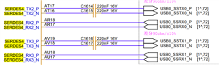
The schematic diagram of our USB and SERDES is shown in the following figure.

Connect USB 0 to LAN2 and LAN3 of serdes4.
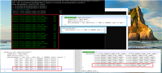


设备树配置如下:

  • Hi quansheng zhu

    Can you share all the steps in working and non working condition you are following to keep the device in the fastboot mode.

    Also help share the logs as well.

    Reagards
    Diwakar

  • Operating steps:

    1. Firstly, stop in uboot mode through the serial port.

    2. Enter fastboot 0 to enter fastboot mode.

    3. Enter fastboot device in the cmd window.

    If you follow the configuration in the problem and configure the serdes4 corresponding to the schematic diagram, there will be no device display after the third step is executed. However, according to the original configuration of serdes0 on the development board, after the third step is executed, the device can appear.


  • Hi quansheng zhu

    Thats weird, Are you able to use USB3.0 in Linux when you configure the serdes as per the schematic ?

    Regards
    Diwakar

  • We printed it on the development board, and the mode is also HIGH SPEED.

    1. So currently, USB3.0 has not been successful?

    2. Does this mean that the serdes configuration has not taken effect?

    3. Based on the assumption of 2, if it does not take effect, why would changing the configuration affect normal functionality?

  • Hi

    1. So currently, USB3.0 has not been successful?

    it has to be in super speed for the USB 3.0.

    2. Does this mean that the serdes configuration has not taken effect?

    Have you made the changes in the linux dtsi as well ?

    3. Based on the assumption of 2, if it does not take effect, why would changing the configuration affect normal functionality?

    Need to check i think you dont need a serdes configuration in uboot but let me check on this part.serdes configuration is just to support usb3.0.

    Regatds
    Diwakar

  • I also modified it to serdes4 in the Linux kernel or disabled serdes4, which will cause the adb that could have been connected to not be able to connect.

    The modification of removing serdes is shown in the following figure:


  • Hi 

    Please share final dtsi file with the changes as per the schematic.

    Wanted to review the configuration are correct or not share both linux as well as uboot dts changes.

    Regards
    Diwakar

  • Our modified device tree source file is attached.

    uboot: k3-j784s4-uboot.txt

    kernel: k3-j784s4-kernel.txt

    Please help troubleshoot issues with serdes and provide solutions. We need the functionality of USB 3.0.

    Tthank you!!!

    // SPDX-License-Identifier: GPL-2.0
    /*
     * Copyright (C) 2022 Texas Instruments Incorporated - https://www.ti.com/
     *
     * Common Processor Board: https://www.ti.com/tool/J721EXCPXEVM
     */
    
    /dts-v1/;
    
    #include "k3-j784s4.dtsi"
    #include <dt-bindings/gpio/gpio.h>
    #include <dt-bindings/net/ti-dp83867.h>
    #include <dt-bindings/phy/phy-cadence.h>
    #include <dt-bindings/phy/phy.h>
    
    / {
    	compatible = "ti,j784s4-evm", "ti,j784s4";
    	model = "Texas Instruments J784S4 EVM";
    
    	chosen {
    		stdout-path = "serial2:115200n8";
    	};
    	aliases {
    		serial2 = &main_uart8;
    		mmc0 = &main_sdhci0;
    		mmc1 = &main_sdhci1;
    		can0 = &mcu_mcan0;
    		can1 = &mcu_mcan1;
    		remoteproc0 = &mcu_r5fss0_core0;
    		remoteproc1 = &mcu_r5fss0_core1;
    		remoteproc2 = &main_r5fss0_core0;
    		remoteproc3 = &main_r5fss0_core1;
    		remoteproc4 = &main_r5fss1_core0;
    		remoteproc5 = &main_r5fss1_core1;
    		remoteproc6 = &main_r5fss2_core0;
    		remoteproc7 = &main_r5fss2_core1;
    		remoteproc8 = &c71_0;
    		remoteproc9 = &c71_1;
    		remoteproc10 = &c71_2;
    		remoteproc11 = &c71_3;
    	};
    
    	memory@80000000 {
    		device_type = "memory";
    		/* 32G RAM */
    		reg = <0x00 0x80000000 0x00 0x80000000>,
    		       <0x08 0x80000000 0x07 0x80000000>;
    	};
    
    	/* Reserving memory regions still pending */
    	reserved_memory: reserved-memory {
    		#address-cells = <2>;
    		#size-cells = <2>;
    		ranges;
    
    		secure_ddr: optee@9e800000 {
    			reg = <0x00 0x9e800000 0x00 0x01800000>;
    			alignment = <0x1000>;
    			no-map;
    		};
    
    		mcu_r5fss0_core0_dma_memory_region: r5f-dma-memory@a0000000 {
    			compatible = "shared-dma-pool";
    			reg = <0x00 0xa0000000 0x00 0x100000>;
    			no-map;
    		};
    
    		mcu_r5fss0_core0_memory_region: r5f-memory@a0100000 {
    			compatible = "shared-dma-pool";
    			reg = <0x00 0xa0100000 0x00 0xf00000>;
    			no-map;
    		};
    
    		mcu_r5fss0_core1_dma_memory_region: r5f-dma-memory@a1000000 {
    			compatible = "shared-dma-pool";
    			reg = <0x00 0xa1000000 0x00 0x100000>;
    			no-map;
    		};
    
    		mcu_r5fss0_core1_memory_region: r5f-memory@a1100000 {
    			compatible = "shared-dma-pool";
    			reg = <0x00 0xa1100000 0x00 0xf00000>;
    			no-map;
    		};
    
    		main_r5fss0_core0_dma_memory_region: r5f-dma-memory@a2000000 {
    			compatible = "shared-dma-pool";
    			reg = <0x00 0xa2000000 0x00 0x100000>;
    			no-map;
    		};
    
    		main_r5fss0_core0_memory_region: r5f-memory@a2100000 {
    			compatible = "shared-dma-pool";
    			reg = <0x00 0xa2100000 0x00 0xf00000>;
    			no-map;
    		};
    
    		main_r5fss0_core1_dma_memory_region: r5f-dma-memory@a3000000 {
    			compatible = "shared-dma-pool";
    			reg = <0x00 0xa3000000 0x00 0x100000>;
    			no-map;
    		};
    
    		main_r5fss0_core1_memory_region: r5f-memory@a3100000 {
    			compatible = "shared-dma-pool";
    			reg = <0x00 0xa3100000 0x00 0xf00000>;
    			no-map;
    		};
    
    		main_r5fss1_core0_dma_memory_region: r5f-dma-memory@a4000000 {
    			compatible = "shared-dma-pool";
    			reg = <0x00 0xa4000000 0x00 0x100000>;
    			no-map;
    		};
    
    		main_r5fss1_core0_memory_region: r5f-memory@a4100000 {
    			compatible = "shared-dma-pool";
    			reg = <0x00 0xa4100000 0x00 0xf00000>;
    			no-map;
    		};
    
    		main_r5fss1_core1_dma_memory_region: r5f-dma-memory@a5000000 {
    			compatible = "shared-dma-pool";
    			reg = <0x00 0xa5000000 0x00 0x100000>;
    			no-map;
    		};
    
    		main_r5fss1_core1_memory_region: r5f-memory@a5100000 {
    			compatible = "shared-dma-pool";
    			reg = <0x00 0xa5100000 0x00 0xf00000>;
    			no-map;
    		};
    
    		main_r5fss2_core0_dma_memory_region: r5f-dma-memory@a6000000 {
    			compatible = "shared-dma-pool";
    			reg = <0x00 0xa6000000 0x00 0x100000>;
    			no-map;
    		};
    
    		main_r5fss2_core0_memory_region: r5f-memory@a6100000 {
    			compatible = "shared-dma-pool";
    			reg = <0x00 0xa6100000 0x00 0xf00000>;
    			no-map;
    		};
    
    		main_r5fss2_core1_dma_memory_region: r5f-dma-memory@a7000000 {
    			compatible = "shared-dma-pool";
    			reg = <0x00 0xa7000000 0x00 0x100000>;
    			no-map;
    		};
    
    		main_r5fss2_core1_memory_region: r5f-memory@a7100000 {
    			compatible = "shared-dma-pool";
    			reg = <0x00 0xa7100000 0x00 0xf00000>;
    			no-map;
    		};
    
    		c71_0_dma_memory_region: c71-dma-memory@a8000000 {
    			compatible = "shared-dma-pool";
    			reg = <0x00 0xa8000000 0x00 0x100000>;
    			no-map;
    		};
    
    		c71_0_memory_region: c71-memory@a8100000 {
    			compatible = "shared-dma-pool";
    			reg = <0x00 0xa8100000 0x00 0xf00000>;
    			no-map;
    		};
    
    		c71_1_dma_memory_region: c71-dma-memory@a9000000 {
    			compatible = "shared-dma-pool";
    			reg = <0x00 0xa9000000 0x00 0x100000>;
    			no-map;
    		};
    
    		c71_1_memory_region: c71-memory@a9100000 {
    			compatible = "shared-dma-pool";
    			reg = <0x00 0xa9100000 0x00 0xf00000>;
    			no-map;
    		};
    
    		c71_2_dma_memory_region: c71-dma-memory@aa000000 {
    			compatible = "shared-dma-pool";
    			reg = <0x00 0xaa000000 0x00 0x100000>;
    			no-map;
    		};
    
    		c71_2_memory_region: c71-memory@aa100000 {
    			compatible = "shared-dma-pool";
    			reg = <0x00 0xaa100000 0x00 0xf00000>;
    			no-map;
    		};
    
    		c71_3_dma_memory_region: c71-dma-memory@ab000000 {
    			compatible = "shared-dma-pool";
    			reg = <0x00 0xab000000 0x00 0x100000>;
    			no-map;
    		};
    
    		c71_3_memory_region: c71-memory@ab100000 {
    			compatible = "shared-dma-pool";
    			reg = <0x00 0xab100000 0x00 0xf00000>;
    			no-map;
    		};
    
    		rtos_ipc_memory_region: ipc-memories@ac000000 {
    			reg = <0x00 0xac000000 0x00 0x03000000>;
    			alignment = <0x1000>;
    			no-map;
    		};
    
    		eth_multicast_memory_region: eth-multicast-memories@adc00000 {
    			reg = <0x00 0xaf000000 0x00 0x2000000>;
    			alignment = <0x1000>;
    			no-map;
    		};
    	};
    
    	evm_12v0: fixedregulator-evm12v0 {
    		/* main supply */
    		compatible = "regulator-fixed";
    		regulator-name = "evm_12v0";
    		regulator-min-microvolt = <12000000>;
    		regulator-max-microvolt = <12000000>;
    		regulator-always-on;
    		regulator-boot-on;
    	};
    
    	vsys_3v3: fixedregulator-vsys3v3 {
    		/* Output of LM5140 */
    		compatible = "regulator-fixed";
    		regulator-name = "vsys_3v3";
    		regulator-min-microvolt = <3300000>;
    		regulator-max-microvolt = <3300000>;
    		vin-supply = <&evm_12v0>;
    		regulator-always-on;
    		regulator-boot-on;
    	};
    
    	vsys_5v0: fixedregulator-vsys5v0 {
    		/* Output of LM5140 */
    		compatible = "regulator-fixed";
    		regulator-name = "vsys_5v0";
    		regulator-min-microvolt = <5000000>;
    		regulator-max-microvolt = <5000000>;
    		vin-supply = <&evm_12v0>;
    		regulator-always-on;
    		regulator-boot-on;
    	};
    
    	vdd_mmc1: fixedregulator-sd {
    		/* Output of TPS22918 */
    		compatible = "regulator-fixed";
    		regulator-name = "vdd_mmc1";
    		regulator-min-microvolt = <3300000>;
    		regulator-max-microvolt = <3300000>;
    		regulator-boot-on;
    		enable-active-high;
    		vin-supply = <&vsys_3v3>;
    		gpio = <&exp2 2 GPIO_ACTIVE_HIGH>;
    	};
    
    	vdd_sd_dv: gpio-regulator-TLV71033 {
    		/* Output of TLV71033 */
    		compatible = "regulator-gpio";
    		regulator-name = "tlv71033";
    		pinctrl-names = "default";
    		pinctrl-0 = <&vdd_sd_dv_pins_default>;
    		regulator-min-microvolt = <1800000>;
    		regulator-max-microvolt = <3300000>;
    		regulator-boot-on;
    		vin-supply = <&vsys_5v0>;
    		gpios = <&main_gpio0 8 GPIO_ACTIVE_HIGH>;
    		states = <1800000 0x0>,
    			 <3300000 0x1>;
    	};
    
    	transceiver1: can-phy1 {
    		compatible = "ti,tcan1042";
    		#phy-cells = <0>;
    		max-bitrate = <5000000>;
    		pinctrl-names = "default";
    		pinctrl-0 = <&mcu_mcan0_gpio_pins_default>;
    		standby-gpios = <&wkup_gpio0 69 GPIO_ACTIVE_HIGH>;
    	};
    
    	transceiver2: can-phy2 {
    		compatible = "ti,tcan1042";
    		#phy-cells = <0>;
    		max-bitrate = <5000000>;
    		pinctrl-names = "default";
    		pinctrl-0 = <&mcu_mcan1_gpio_pins_default>;
    		standby-gpios = <&wkup_gpio0 2 GPIO_ACTIVE_HIGH>;
    	};
    
    	serdes_wiz4: wiz@5050000 {
    			compatible = "ti,j784s4-wiz-10g";
    			#address-cells = <1>;
    			#size-cells = <1>;
    			power-domains = <&k3_pds 407 TI_SCI_PD_EXCLUSIVE>;
    			clocks = <&k3_clks 407 2>, <&k3_clks 407 6>, <&k3_clks 407 10>, <&serdes_refclk>;
    			clock-names = "fck", "core_ref_clk", "core_ref1_clk", "ext_ref_clk";
    			num-lanes = <4>;
    			#reset-cells = <1>;
    			#clock-cells = <1>;
    			ranges = <0x05050000 0x0 0x05050000 0x00010000>,
    					<0xa030a00 0x0 0xa030a00 0x40>;
    
    			assigned-clocks = <&k3_clks 407 6>;
    			assigned-clock-parents = <&k3_clks 407 10>;
    
    			status = "disabled";
    
    			serdes4: serdes@5050000 {
    					compatible = "ti,j721e-serdes-10g";
    					reg = <0x05050000 0x00010000>,
    						<0xa030a00 0x40>;
    					reg-names = "torrent_phy";
    					resets = <&serdes_wiz4 0>;
    					reset-names = "torrent_reset";
    					clocks = <&serdes_wiz4 TI_WIZ_PLL0_REFCLK>,
    							<&serdes_wiz4 TI_WIZ_PHY_EN_REFCLK>;
    					clock-names = "refclk", "phy_en_refclk";
    					assigned-clocks = <&serdes_wiz4 TI_WIZ_PLL0_REFCLK>,
    									<&serdes_wiz4 TI_WIZ_PLL1_REFCLK>,
    									<&serdes_wiz4 TI_WIZ_REFCLK_DIG>;
    					assigned-clock-parents = <&k3_clks 407 6>,
    											<&k3_clks 407 6>,
    											<&k3_clks 407 6>;
    					#address-cells = <1>;
    					#size-cells = <0>;
    					#clock-cells = <1>;
    
    					status = "disabled";
    			};
    	};
    };
    
    &wkup_pmx0 {
    	mcu_fss0_ospi0_pins_default: mcu-fss0-ospi0-pins-default {
    		pinctrl-single,pins = <
    			J784S4_WKUP_IOPAD(0x000, PIN_OUTPUT, 0) /* (E32) MCU_OSPI0_CLK */
    			J784S4_WKUP_IOPAD(0x02c, PIN_OUTPUT, 0) /* (A32) MCU_OSPI0_CSn0 */
    			J784S4_WKUP_IOPAD(0x00c, PIN_INPUT, 0) /* (B33) MCU_OSPI0_D0 */
    			J784S4_WKUP_IOPAD(0x010, PIN_INPUT, 0) /* (B32) MCU_OSPI0_D1 */
    			J784S4_WKUP_IOPAD(0x014, PIN_INPUT, 0) /* (C33) MCU_OSPI0_D2 */
    			J784S4_WKUP_IOPAD(0x018, PIN_INPUT, 0) /* (C35) MCU_OSPI0_D3 */
    			J784S4_WKUP_IOPAD(0x01c, PIN_INPUT, 0) /* (D33) MCU_OSPI0_D4 */
    			J784S4_WKUP_IOPAD(0x020, PIN_INPUT, 0) /* (D34) MCU_OSPI0_D5 */
    			J784S4_WKUP_IOPAD(0x024, PIN_INPUT, 0) /* (E34) MCU_OSPI0_D6 */
    			J784S4_WKUP_IOPAD(0x028, PIN_INPUT, 0) /* (E33) MCU_OSPI0_D7 */
    			J784S4_WKUP_IOPAD(0x008, PIN_INPUT, 0) /* (C34) MCU_OSPI0_DQS */
    			J784S4_WKUP_IOPAD(0x03c, PIN_OUTPUT, 6) /* (C32) MCU_OSPI0_CSn3.MCU_OSPI0_ECC_FAIL */
    			J784S4_WKUP_IOPAD(0x038, PIN_OUTPUT, 6) /* (B34) MCU_OSPI0_CSn2.MCU_OSPI0_RESET_OUT0 */
    		>;
    	};
    
    	mcu_cpsw_pins_default: mcu-cpsw-pins-default {
    		pinctrl-single,pins = <
    			J784S4_WKUP_IOPAD(0x094, PIN_INPUT, 0) /* (A35) MCU_RGMII1_RD0 */
    			J784S4_WKUP_IOPAD(0x090, PIN_INPUT, 0) /* (B36) MCU_RGMII1_RD1 */
    			J784S4_WKUP_IOPAD(0x08c, PIN_INPUT, 0) /* (C36) MCU_RGMII1_RD2 */
    			J784S4_WKUP_IOPAD(0x088, PIN_INPUT, 0) /* (D36) MCU_RGMII1_RD3 */
    			J784S4_WKUP_IOPAD(0x084, PIN_INPUT, 0) /* (B37) MCU_RGMII1_RXC */
    			J784S4_WKUP_IOPAD(0x06c, PIN_INPUT, 0) /* (C37) MCU_RGMII1_RX_CTL */
    			J784S4_WKUP_IOPAD(0x07c, PIN_OUTPUT, 0) /* (D37) MCU_RGMII1_TD0 */
    			J784S4_WKUP_IOPAD(0x078, PIN_OUTPUT, 0) /* (D38) MCU_RGMII1_TD1 */
    			J784S4_WKUP_IOPAD(0x074, PIN_OUTPUT, 0) /* (E37) MCU_RGMII1_TD2 */
    			J784S4_WKUP_IOPAD(0x070, PIN_OUTPUT, 0) /* (E38) MCU_RGMII1_TD3 */
    			J784S4_WKUP_IOPAD(0x080, PIN_OUTPUT, 0) /* (E36) MCU_RGMII1_TXC */
    			J784S4_WKUP_IOPAD(0x068, PIN_OUTPUT, 0) /* (C38) MCU_RGMII1_TX_CTL */
    		>;
    	};
    
    	mcu_mdio_pins_default: mcu-mdio-pins-default {
    		pinctrl-single,pins = <
    			J784S4_WKUP_IOPAD(0x09c, PIN_OUTPUT, 0) /* (A36) MCU_MDIO0_MDC */
    			J784S4_WKUP_IOPAD(0x098, PIN_INPUT, 0) /* (B35) MCU_MDIO0_MDIO */
    		>;
    	};
    
    	mcu_mcan0_pins_default: mcu-mcan0-pins-default {
    		pinctrl-single,pins = <
    			J784S4_WKUP_IOPAD(0x0bc, PIN_INPUT, 0) /* (F38) MCU_MCAN0_RX */
    			J784S4_WKUP_IOPAD(0x0b8, PIN_OUTPUT, 0) /* (K33) MCU_MCAN0_TX */
    		>;
    	};
    
    	mcu_mcan1_pins_default: mcu-mcan1-pins-default {
    		pinctrl-single,pins = <
    			J784S4_WKUP_IOPAD(0x0d4, PIN_INPUT, 0) /* (K36) WKUP_GPIO0_5.MCU_MCAN1_RX */
    			J784S4_WKUP_IOPAD(0x0d0, PIN_OUTPUT, 0) /* (H35) WKUP_GPIO0_4.MCU_MCAN1_TX */
    		>;
    	};
    
    	mcu_mcan0_gpio_pins_default: mcu-mcan0-gpio-pins-default {
    		pinctrl-single,pins = <
    			J784S4_WKUP_IOPAD(0x0a8, PIN_INPUT, 7) /* (J38) MCU_SPI0_D1.WKUP_GPIO0_69 */
    		>;
    	};
    
    	mcu_mcan1_gpio_pins_default: mcu-mcan1-gpio-pins-default {
    		pinctrl-single,pins = <
    			J784S4_WKUP_IOPAD(0x0c8, PIN_INPUT, 7) /* (J35) WKUP_GPIO0_2 */
    		>;
    	};
    
    	mcu_fss0_ospi1_pins_default: mcu-fss0-ospi1-pins-default {
    		pinctrl-single,pins = <
    			J784S4_WKUP_IOPAD(0x040, PIN_OUTPUT, 0) /* (F32) MCU_OSPI1_CLK */
    			J784S4_WKUP_IOPAD(0x05c, PIN_OUTPUT, 0) /* (G32) MCU_OSPI1_CSn0 */
    			J784S4_WKUP_IOPAD(0x04c, PIN_INPUT, 0) /* (E35) MCU_OSPI1_D0 */
    			J784S4_WKUP_IOPAD(0x050, PIN_INPUT, 0) /* (D31) MCU_OSPI1_D1 */
    			J784S4_WKUP_IOPAD(0x054, PIN_INPUT, 0) /* (G31) MCU_OSPI1_D2 */
    			J784S4_WKUP_IOPAD(0x058, PIN_INPUT, 0) /* (F33) MCU_OSPI1_D3 */
    			J784S4_WKUP_IOPAD(0x048, PIN_INPUT, 0) /* (F31) MCU_OSPI1_DQS */
    			J784S4_WKUP_IOPAD(0x044, PIN_INPUT, 0) /* (C31) MCU_OSPI1_LBCLKO */
    		>;
    	};
    };
    
    &main_pmx0 {
    	main_i2c0_pins_default: main-i2c0-pins-default {
    		pinctrl-single,pins = <
    			J784S4_IOPAD(0x0e0, PIN_INPUT_PULLUP, 0) /* (AN36) I2C0_SCL */
    			J784S4_IOPAD(0x0e4, PIN_INPUT_PULLUP, 0) /* (AP37) I2C0_SDA */
    		>;
    	};
    
    	main_mcan16_pins_default: main-mcan16-pins-default {
    		pinctrl-single,pins = <
    			J784S4_IOPAD(0x028, PIN_INPUT, 0) /* (AE33) MCAN16_RX */
    			J784S4_IOPAD(0x024, PIN_OUTPUT, 0) /* (AH34) MCAN16_TX */
    		>;
    	};
    
    	main_uart8_pins_default: main-uart8-pins-default {
    		pinctrl-single,pins = <
    			J784S4_IOPAD(0x040, PIN_INPUT, 14) /* (AF37) MCASP0_AXR0.UART8_CTSn */
    			J784S4_IOPAD(0x044, PIN_OUTPUT, 14) /* (AG37) MCASP0_AXR1.UART8_RTSn */
    			J784S4_IOPAD(0x0d0, PIN_INPUT, 11) /* (AP38) SPI0_CS1.UART8_RXD */
    			J784S4_IOPAD(0x0d4, PIN_OUTPUT, 11) /* (AN38) SPI0_CLK.UART8_TXD */
    		>;
    	};
    
    	main_i2c3_pins_default: main-i2c3-pins-default {
    		pinctrl-single,pins = <
    			J784S4_IOPAD(0x064, PIN_INPUT_PULLUP, 13) /* (AF38) MCAN0_TX.I2C3_SCL */
    			J784S4_IOPAD(0x060, PIN_INPUT_PULLUP, 13) /* (AE36) MCASP2_AXR1.I2C3_SDA */
    		>;
    	};
    
    	main_mmc1_pins_default: main-mmc1-pins-default {
    		pinctrl-single,pins = <
    			J784S4_IOPAD(0x104, PIN_INPUT, 0) /* (AB38) MMC1_CLK */
    			J784S4_IOPAD(0x108, PIN_INPUT, 0) /* (AB36) MMC1_CMD */
    			J784S4_IOPAD(0x0fc, PIN_INPUT, 0) /* (AA33) MMC1_DAT0 */
    			J784S4_IOPAD(0x0f8, PIN_INPUT, 0) /* (AB34) MMC1_DAT1 */
    			J784S4_IOPAD(0x0f4, PIN_INPUT, 0) /* (AA32) MMC1_DAT2 */
    			J784S4_IOPAD(0x0f0, PIN_INPUT, 0) /* (AC38) MMC1_DAT3 */
    			J784S4_IOPAD(0x0e8, PIN_INPUT, 8) /* (AR38) TIMER_IO0.MMC1_SDCD */
    		>;
    	};
    
    	vdd_sd_dv_pins_default: vdd-sd-dv-pins-default {
    		pinctrl-single,pins = <
    			J784S4_IOPAD(0x020, PIN_INPUT, 7) /* (AJ35) MCAN15_RX.GPIO0_8 */
    		>;
    	};
    
    	main_usbss0_pins_default: main-usbss0-pins-default {
    		pinctrl-single,pins = <
    			J784S4_IOPAD(0x02c, PIN_OUTPUT, 14) /* (AL32) GPIO0_11.USB0_DRVVBUS */
    		>;
    	};


    };
    
    &main_i2c0 {
    	pinctrl-names = "default";
    	pinctrl-0 = <&main_i2c0_pins_default>;
    	clock-frequency = <400000>;
    
    	exp1: gpio@20 {
    		compatible = "ti,tca6416";
    		reg = <0x20>;
    		gpio-controller;
    		#gpio-cells = <2>;
    		gpio-line-names = "PCIE1_2L_MODE_SEL", "PCIE1_4L_PERSTZ", "PCIE1_2L_RC_RSTZ",
    				  "PCIE1_2L_EP_RST_EN", "PCIE0_4L_MODE_SEL", "PCIE0_4L_PERSTZ",
    				  "PCIE0_4L_RC_RSTZ", "PCIE0_4L_EP_RST_EN", "PCIE1_4L_PRSNT#",
    				  "PCIE0_4L_PRSNT#", "CDCI1_OE1/OE4", "CDCI1_OE2/OE3",
    				  "AUDIO_MUX_SEL", "EXP_MUX2", "EXP_MUX3", "GESI_EXP_PHY_RSTZ";
    	};
    
    	exp2: gpio@22 {
    		compatible = "ti,tca6424";
    		reg = <0x22>;
    		gpio-controller;
    		#gpio-cells = <2>;
    		gpio-line-names = "R_GPIO_RGMII1_RST", "ENET2_I2CMUX_SEL", "GPIO_USD_PWR_EN",
    				  "USBC_PWR_EN", "USBC_MODE_SEL1", "USBC_MODE_SEL0",
    				  "GPIO_LIN_EN", "R_CAN_STB", "CTRL_PM_I2C_OE#",
    				  "ENET2_EXP_PWRDN", "ENET2_EXP_SPARE2", "CDCI2_RSTZ",
    				  "USB2.0_MUX_SEL", "CANUART_MUX_SEL0", "CANUART_MUX2_SEL1",
    				  "CANUART_MUX1_SEL1", "ENET1_EXP_PWRDN", "ENET1_EXP_RESETZ",
    				  "ENET1_I2CMUX_SEL", "ENET1_EXP_SPARE2", "ENET2_EXP_RESETZ",
    				  "USER_INPUT1", "USER_LED1", "USER_LED2";
    	};
    };
    
    &ospi0 {
    	pinctrl-names = "default";
    	pinctrl-0 = <&mcu_fss0_ospi0_pins_default>;
    
    	flash@0 {
    		compatible = "jedec,spi-nor";
    		reg = <0x0>;
    		spi-tx-bus-width = <8>;
    		spi-rx-bus-width = <8>;
    		spi-max-frequency = <25000000>;
    		cdns,tshsl-ns = <60>;
    		cdns,tsd2d-ns = <60>;
    		cdns,tchsh-ns = <60>;
    		cdns,tslch-ns = <60>;
    		cdns,read-delay = <4>;
    		cdns,phy-mode;
    		#address-cells = <1>;
    		#size-cells = <1>;
    	};
    };
    
    &mailbox0_cluster0 {
    	interrupts = <436>;
    
    	mbox_mcu_r5fss0_core0: mbox-mcu-r5fss0-core0 {
    		ti,mbox-rx = <0 0 0>;
    		ti,mbox-tx = <1 0 0>;
    	};
    
    	mbox_mcu_r5fss0_core1: mbox-mcu-r5fss0-core1 {
    		ti,mbox-rx = <2 0 0>;
    		ti,mbox-tx = <3 0 0>;
    	};
    };
    
    &mailbox0_cluster1 {
    	interrupts = <432>;
    
    	mbox_main_r5fss0_core0: mbox-main-r5fss0-core0 {
    		ti,mbox-rx = <0 0 0>;
    		ti,mbox-tx = <1 0 0>;
    	};
    
    	mbox_main_r5fss0_core1: mbox-main-r5fss0-core1 {
    		ti,mbox-rx = <2 0 0>;
    		ti,mbox-tx = <3 0 0>;
    	};
    };
    
    &mailbox0_cluster2 {
    	interrupts = <428>;
    
    	mbox_main_r5fss1_core0: mbox-main-r5fss1-core0 {
    		ti,mbox-rx = <0 0 0>;
    		ti,mbox-tx = <1 0 0>;
    	};
    
    	mbox_main_r5fss1_core1: mbox-main-r5fss1-core1 {
    		ti,mbox-rx = <2 0 0>;
    		ti,mbox-tx = <3 0 0>;
    	};
    };
    
    &mailbox0_cluster3 {
    	interrupts = <424>;
    
    	mbox_main_r5fss2_core0: mbox-main-r5fss2-core0 {
    		ti,mbox-rx = <0 0 0>;
    		ti,mbox-tx = <1 0 0>;
    	};
    
    	mbox_main_r5fss2_core1: mbox-main-r5fss2-core1 {
    		ti,mbox-rx = <2 0 0>;
    		ti,mbox-tx = <3 0 0>;
    	};
    };
    
    &mailbox0_cluster4 {
    	interrupts = <420>;
    
    	mbox_c71_0: mbox-c71-0 {
    		ti,mbox-rx = <0 0 0>;
    		ti,mbox-tx = <1 0 0>;
    	};
    
    	mbox_c71_1: mbox-c71-1 {
    		ti,mbox-rx = <2 0 0>;
    		ti,mbox-tx = <3 0 0>;
    	};
    };
    
    &mailbox0_cluster5 {
    	interrupts = <416>;
    
    	mbox_c71_2: mbox-c71-2 {
    		ti,mbox-rx = <0 0 0>;
    		ti,mbox-tx = <1 0 0>;
    	};
    
    	mbox_c71_3: mbox-c71-3 {
    		ti,mbox-rx = <2 0 0>;
    		ti,mbox-tx = <3 0 0>;
    	};
    };
    
    &mailbox0_cluster6 {
    	status = "disabled";
    };
    
    &mailbox0_cluster7 {
    	status = "disabled";
    };
    
    &mailbox0_cluster8 {
    	status = "disabled";
    };
    
    &mailbox0_cluster9 {
    	status = "disabled";
    };
    
    &mailbox0_cluster10 {
    	status = "disabled";
    };
    
    &mailbox0_cluster11 {
    	status = "disabled";
    };
    
    &mailbox1_cluster0 {
    	status = "disabled";
    };
    
    &mailbox1_cluster1 {
    	status = "disabled";
    };
    
    &mailbox1_cluster2 {
    	status = "disabled";
    };
    
    &mailbox1_cluster3 {
    	status = "disabled";
    };
    
    &mailbox1_cluster4 {
    	status = "disabled";
    };
    
    &mailbox1_cluster5 {
    	status = "disabled";
    };
    
    &mailbox1_cluster6 {
    	status = "disabled";
    };
    
    &mailbox1_cluster7 {
    	status = "disabled";
    };
    
    &mailbox1_cluster8 {
    	status = "disabled";
    };
    
    &mailbox1_cluster9 {
    	status = "disabled";
    };
    
    &mailbox1_cluster10 {
    	status = "disabled";
    };
    
    &mailbox1_cluster11 {
    	status = "disabled";
    };
    
    &mcu_r5fss0_core0 {
    	mboxes = <&mailbox0_cluster0 &mbox_mcu_r5fss0_core0>;
    	memory-region = <&mcu_r5fss0_core0_dma_memory_region>,
    			<&mcu_r5fss0_core0_memory_region>;
    };
    
    &mcu_r5fss0_core1 {
    	mboxes = <&mailbox0_cluster0 &mbox_mcu_r5fss0_core1>;
    	memory-region = <&mcu_r5fss0_core1_dma_memory_region>,
    			<&mcu_r5fss0_core1_memory_region>;
    };
    
    &main_r5fss0_core0 {
    	mboxes = <&mailbox0_cluster1 &mbox_main_r5fss0_core0>;
    	memory-region = <&main_r5fss0_core0_dma_memory_region>,
    			<&main_r5fss0_core0_memory_region>;
    };
    
    &main_r5fss0_core1 {
    	mboxes = <&mailbox0_cluster1 &mbox_main_r5fss0_core1>;
    	memory-region = <&main_r5fss0_core1_dma_memory_region>,
    			<&main_r5fss0_core1_memory_region>;
    };
    
    &main_r5fss1_core0 {
    	mboxes = <&mailbox0_cluster2 &mbox_main_r5fss1_core0>;
    	memory-region = <&main_r5fss1_core0_dma_memory_region>,
    			<&main_r5fss1_core0_memory_region>;
    };
    
    &main_r5fss1_core1 {
    	mboxes = <&mailbox0_cluster2 &mbox_main_r5fss1_core1>;
    	memory-region = <&main_r5fss1_core1_dma_memory_region>,
    			<&main_r5fss1_core1_memory_region>;
    };
    
    &main_r5fss2_core0 {
    	mboxes = <&mailbox0_cluster3 &mbox_main_r5fss2_core0>;
    	memory-region = <&main_r5fss2_core0_dma_memory_region>,
    			<&main_r5fss2_core0_memory_region>;
    };
    
    &main_r5fss2_core1 {
    	mboxes = <&mailbox0_cluster3 &mbox_main_r5fss2_core1>;
    	memory-region = <&main_r5fss2_core1_dma_memory_region>,
    			<&main_r5fss2_core1_memory_region>;
    };
    
    &c71_0 {
    	mboxes = <&mailbox0_cluster4 &mbox_c71_0>;
    	memory-region = <&c71_0_dma_memory_region>,
    			<&c71_0_memory_region>;
    };
    
    &c71_1 {
    	mboxes = <&mailbox0_cluster4 &mbox_c71_1>;
    	memory-region = <&c71_1_dma_memory_region>,
    			<&c71_1_memory_region>;
    };
    
    &c71_2 {
    	mboxes = <&mailbox0_cluster5 &mbox_c71_2>;
    	memory-region = <&c71_2_dma_memory_region>,
    			<&c71_2_memory_region>;
    };
    
    &c71_3 {
    	mboxes = <&mailbox0_cluster5 &mbox_c71_3>;
    	memory-region = <&c71_3_dma_memory_region>,
    			<&c71_3_memory_region>;
    };
    
    &main_gpio2 {
    	status = "disabled";
    };
    
    &main_gpio4 {
    	status = "disabled";
    };
    
    &main_gpio6 {
    	status = "disabled";
    };
    
    &wkup_gpio1 {
    	status = "disabled";
    };
    
    &wkup_uart0 {
    	status = "reserved";
    };
    
    &main_uart0 {
    	status = "disabled";
    };
    
    &main_uart1 {
    	status = "disabled";
    };
    
    &main_uart2 {
    	status = "disabled";
    };
    
    &main_uart3 {
    	status = "disabled";
    };
    
    &main_uart4 {
    	status = "disabled";
    };
    
    &main_uart5 {
    	status = "disabled";
    };
    
    &main_uart6 {
    	status = "disabled";
    };
    
    &main_uart7 {
    	status = "disabled";
    };
    
    &main_uart8 {
    	status = "okay";
    	pinctrl-names = "default";
    	pinctrl-0 = <&main_uart8_pins_default>;
    	/* Shared with TFA on this platform */
    	power-domains = <&k3_pds 395 TI_SCI_PD_SHARED>;
    };
    
    &main_uart9 {
    	status = "disabled";
    };
    
    &main_i2c1 {
    	status = "disabled";
    };
    
    &main_i2c2 {
    	status = "disabled";
    };
    
    &main_i2c3 {
    	status = "disabled";
    };
    
    &main_i2c4 {
    	status = "disabled";
    };
    
    &main_i2c5 {
    	status = "disabled";
    };
    
    &main_i2c6 {
    	status = "disabled";
    };
    
    &main_sdhci0 {
    	/* eMMC */
    	non-removable;
    	ti,driver-strength-ohm = <50>;
    	/* Disabling all the UHS modes, to re-enable UHS modes, remove the
    	 * sdhci-caps-mask and no-1-8-v property. */
    	sdhci-caps-mask = <0x00000007 0x00000000>;
    	no-1-8-v;
    	disable-wp;
    };
    
    &main_sdhci1 {
    	/* SD card */
    	pinctrl-0 = <&main_mmc1_pins_default>;
    	pinctrl-names = "default";
    	disable-wp;
    	vmmc-supply = <&vdd_mmc1>;
    	vqmmc-supply = <&vdd_sd_dv>;
    	/* Disabling all the UHS modes, to re-enable UHS modes, remove the
    	 * sdhci-caps-mask and no-1-8-v property. */
    	sdhci-caps-mask = <0x00000007 0x00000000>;
    	no-1-8-v;
    };
    
    &mcu_cpsw {
    	pinctrl-names = "default";
    	pinctrl-0 = <&mcu_cpsw_pins_default &mcu_mdio_pins_default>;
    };
    
    &davinci_mdio {
    	mcu_phy0: ethernet-phy@0 {
    		reg = <0>;
    		ti,rx-internal-delay = <DP83867_RGMIIDCTL_2_00_NS>;
    		ti,fifo-depth = <DP83867_PHYCR_FIFO_DEPTH_4_B_NIB>;
    		ti,min-output-impedance;
    	};
    };
    
    &main_cpsw_mdio {
    	main_phy0: ethernet-phy@0 {
    		reg = <0>;
    		ti,rx-internal-delay = <DP83867_RGMIIDCTL_2_00_NS>;
    		ti,fifo-depth = <DP83867_PHYCR_FIFO_DEPTH_4_B_NIB>;
    		ti,min-output-impedance;
    	};
    };
    
    &cpsw_port1 {
    	phy-mode = "rgmii-rxid";
    	phy-handle = <&mcu_phy0>;
    };
    
    &main_cpsw_port1 {
    	phy-mode = "rgmii-rxid";
    	phy-handle = <&main_phy0>;
    };
    
    &serdes_ln_ctrl {
    	idle-states = <J784S4_SERDES0_LANE0_PCIE1_LANE0>, <J784S4_SERDES0_LANE1_PCIE1_LANE1>,
    		      <J784S4_SERDES0_LANE2_PCIE1_LANE2>, <J784S4_SERDES0_LANE3_PCIE1_LANE3>,
    		      <J784S4_SERDES1_LANE0_QSGMII_LANE3>, <J784S4_SERDES1_LANE1_QSGMII_LANE4>,
    		      <J784S4_SERDES1_LANE2_QSGMII_LANE1>, <J784S4_SERDES1_LANE3_QSGMII_LANE2>,
    		      <J784S4_SERDES2_LANE0_QSGMII_LANE5>, <J784S4_SERDES2_LANE1_QSGMII_LANE6>,
    		      <J784S4_SERDES2_LANE2_QSGMII_LANE7>, <J784S4_SERDES2_LANE3_QSGMII_LANE8>,
    		      <J784S4_SERDES4_LANE0_EDP_LANE0>, <J784S4_SERDES4_LANE1_EDP_LANE1>,
    		      <J784S4_SERDES4_LANE2_IP3_UNUSED>, <J784S4_SERDES4_LANE3_USB>;
    };
    
    &serdes_refclk {
    	clock-frequency = <100000000>;
    };
    
    &serdes4 {
    	serdes4_usb_link: link@3 {
    		reg = <3>;
    		cdns,num-lanes = <1>;
    		#phy-cells = <0>;
    		cdns,phy-type = <PHY_TYPE_USB3>;
    		resets = <&serdes_wiz4 4>;
    	};
    };
    
    &serdes_wiz4 {
    	typec-dir-gpios = <&wkup_gpio0 40 GPIO_ACTIVE_HIGH>;
    	typec-dir-debounce-ms = <700>;  /* TUSB321, tCCB_DEFAULT 133 ms */
    };
    
    &usb_serdes_mux {
    	idle-states = <0>; /* USB0 to SERDES lane 3 */
    };
    
    &usbss0 {
    	pinctrl-0 = <&main_usbss0_pins_default>;
    	pinctrl-names = "default";
    	ti,vbus-divider;
    };
    
    &usb0 {
    	dr_mode = "otg";
    	maximum-speed = "super-speed";
    	phys = <&serdes4_usb_link>;
    	phy-names = "cdns3,usb3-phy";
    };
    
    &ospi1 {
    	pinctrl-names = "default";
    	pinctrl-0 = <&mcu_fss0_ospi1_pins_default>;
    
    	flash@0{
    		compatible = "jedec,spi-nor";
    		reg = <0x0>;
    		spi-tx-bus-width = <1>;
    		spi-rx-bus-width = <4>;
    		spi-max-frequency = <40000000>;
    		cdns,tshsl-ns = <60>;
    		cdns,tsd2d-ns = <60>;
    		cdns,tchsh-ns = <60>;
    		cdns,tslch-ns = <60>;
    		cdns,read-delay = <2>;
    		#address-cells = <1>;
    		#size-cells = <1>;
    	};
    };
    
    &mcu_mcan0 {
    	pinctrl-names = "default";
    	pinctrl-0 = <&mcu_mcan0_pins_default>;
    	phys = <&transceiver1>;
    };
    
    &mcu_mcan1 {
    	pinctrl-names = "default";
    	pinctrl-0 = <&mcu_mcan1_pins_default>;
    	phys = <&transceiver2>;
    };
    
    
    &main_mcan0 {
    	status = "disabled";
    };
    
    &main_mcan1 {
    	status = "disabled";
    };
    
    &main_mcan2 {
    	status = "disabled";
    };
    
    &main_mcan3 {
    	status = "disabled";
    };
    
    &main_mcan4 {
    	status = "disabled";
    };
    
    &main_mcan5 {
    	status = "disabled";
    };
    
    &main_mcan6 {
    	status = "disabled";
    };
    
    &main_mcan7 {
    	status = "disabled";
    };
    
    &main_mcan8 {
    	status = "disabled";
    };
    
    &main_mcan9 {
    	status = "disabled";
    };
    
    &main_mcan10 {
    	status = "disabled";
    };
    
    &main_mcan11 {
    	status = "disabled";
    };
    
    &main_mcan12 {
    	status = "disabled";
    };
    
    &main_mcan13 {
    	status = "disabled";
    };
    
    &main_mcan14 {
    	status = "disabled";
    };
    
    &main_mcan15 {
    	status = "disabled";
    };
    
    &main_mcan16 {
    	status = "disabled";
    };
    
    &main_mcan17 {
    	status = "disabled";
    };
    
    // SPDX-License-Identifier: GPL-2.0
    /*
     * Copyright (C) 2022 Texas Instruments Incorporated - https://www.ti.com/
     *
     * Common Processor Board: https://www.ti.com/tool/J721EXCPXEVM
     */
    
    /dts-v1/;
    
    #include <dt-bindings/net/ti-dp83867.h>
    #include <dt-bindings/gpio/gpio.h>
    #include "k3-j784s4.dtsi"
    
    / {
    	compatible = "ti,j784s4-evm", "ti,j784s4";
    	model = "Texas Instruments J784S4 EVM";
    
    	chosen {
    		stdout-path = "serial2:115200n8";
    	};
    
    	aliases {
    		serial2 = &main_uart8;
    		mmc0 = &main_sdhci0;
    		mmc1 = &main_sdhci1;
    		i2c0 = &main_i2c0;
    	};
    
    	memory@80000000 {
    		device_type = "memory";
    		/* 32G RAM */
    		reg = <0x00 0x80000000 0x00 0x80000000>,
    		      <0x08 0x80000000 0x07 0x80000000>;
    	};
    
    	/* Reserving memory regions still pending */
    	reserved_memory: reserved-memory {
    		#address-cells = <2>;
    		#size-cells = <2>;
    		ranges;
    
    		secure_ddr: optee@9e800000 {
    			reg = <0x00 0x9e800000 0x00 0x01800000>;
    			alignment = <0x1000>;
    			no-map;
    		};
    
    		mcu_r5fss0_core0_dma_memory_region: r5f-dma-memory@a0000000 {
    			compatible = "shared-dma-pool";
    			reg = <0x00 0xa0000000 0x00 0x100000>;
    			no-map;
    		};
    
    		mcu_r5fss0_core0_memory_region: r5f-memory@a0100000 {
    			compatible = "shared-dma-pool";
    			reg = <0x00 0xa0100000 0x00 0xf00000>;
    			no-map;
    		};
    
    		mcu_r5fss0_core1_dma_memory_region: r5f-dma-memory@a1000000 {
    			compatible = "shared-dma-pool";
    			reg = <0x00 0xa1000000 0x00 0x100000>;
    			no-map;
    		};
    
    		mcu_r5fss0_core1_memory_region: r5f-memory@a1100000 {
    			compatible = "shared-dma-pool";
    			reg = <0x00 0xa1100000 0x00 0xf00000>;
    			no-map;
    		};
    
    		main_r5fss0_core0_dma_memory_region: r5f-dma-memory@a2000000 {
    			compatible = "shared-dma-pool";
    			reg = <0x00 0xa2000000 0x00 0x100000>;
    			no-map;
    		};
    
    		main_r5fss0_core0_memory_region: r5f-memory@a2100000 {
    			compatible = "shared-dma-pool";
    			reg = <0x00 0xa2100000 0x00 0xf00000>;
    			no-map;
    		};
    
    		main_r5fss0_core1_dma_memory_region: r5f-dma-memory@a3000000 {
    			compatible = "shared-dma-pool";
    			reg = <0x00 0xa3000000 0x00 0x100000>;
    			no-map;
    		};
    
    		main_r5fss0_core1_memory_region: r5f-memory@a3100000 {
    			compatible = "shared-dma-pool";
    			reg = <0x00 0xa3100000 0x00 0xf00000>;
    			no-map;
    		};
    
    		main_r5fss1_core0_dma_memory_region: r5f-dma-memory@a4000000 {
    			compatible = "shared-dma-pool";
    			reg = <0x00 0xa4000000 0x00 0x100000>;
    			no-map;
    		};
    
    		main_r5fss1_core0_memory_region: r5f-memory@a4100000 {
    			compatible = "shared-dma-pool";
    			reg = <0x00 0xa4100000 0x00 0xf00000>;
    			no-map;
    		};
    
    		main_r5fss1_core1_dma_memory_region: r5f-dma-memory@a5000000 {
    			compatible = "shared-dma-pool";
    			reg = <0x00 0xa5000000 0x00 0x100000>;
    			no-map;
    		};
    
    		main_r5fss1_core1_memory_region: r5f-memory@a5100000 {
    			compatible = "shared-dma-pool";
    			reg = <0x00 0xa5100000 0x00 0xf00000>;
    			no-map;
    		};
    
    		main_r5fss2_core0_dma_memory_region: r5f-dma-memory@a6000000 {
    			compatible = "shared-dma-pool";
    			reg = <0x00 0xa6000000 0x00 0x100000>;
    			no-map;
    		};
    
    		main_r5fss2_core0_memory_region: r5f-memory@a6100000 {
    			compatible = "shared-dma-pool";
    			reg = <0x00 0xa6100000 0x00 0xf00000>;
    			no-map;
    		};
    
    		main_r5fss2_core1_dma_memory_region: r5f-dma-memory@a7000000 {
    			compatible = "shared-dma-pool";
    			reg = <0x00 0xa7000000 0x00 0x100000>;
    			no-map;
    		};
    
    		main_r5fss2_core1_memory_region: r5f-memory@a7100000 {
    			compatible = "shared-dma-pool";
    			reg = <0x00 0xa7100000 0x00 0xf00000>;
    			no-map;
    		};
    
    		c71_0_dma_memory_region: c71-dma-memory@a8000000 {
    			compatible = "shared-dma-pool";
    			reg = <0x00 0xa8000000 0x00 0x100000>;
    			no-map;
    		};
    
    		c71_0_memory_region: c71-memory@a8100000 {
    			compatible = "shared-dma-pool";
    			reg = <0x00 0xa8100000 0x00 0xf00000>;
    			no-map;
    		};
    
    		c71_1_dma_memory_region: c71-dma-memory@a9000000 {
    			compatible = "shared-dma-pool";
    			reg = <0x00 0xa9000000 0x00 0x100000>;
    			no-map;
    		};
    
    		c71_1_memory_region: c71-memory@a9100000 {
    			compatible = "shared-dma-pool";
    			reg = <0x00 0xa9100000 0x00 0xf00000>;
    			no-map;
    		};
    
    		c71_2_dma_memory_region: c71-dma-memory@aa000000 {
    			compatible = "shared-dma-pool";
    			reg = <0x00 0xaa000000 0x00 0x100000>;
    			no-map;
    		};
    
    		c71_2_memory_region: c71-memory@aa100000 {
    			compatible = "shared-dma-pool";
    			reg = <0x00 0xaa100000 0x00 0xf00000>;
    			no-map;
    		};
    
    		c71_3_dma_memory_region: c71-dma-memory@ab000000 {
    			compatible = "shared-dma-pool";
    			reg = <0x00 0xab000000 0x00 0x100000>;
    			no-map;
    		};
    
    		c71_3_memory_region: c71-memory@ab100000 {
    			compatible = "shared-dma-pool";
    			reg = <0x00 0xab100000 0x00 0xf00000>;
    			no-map;
    		};
    	};
    
    	evm_12v0: regulator-evm12v0 {
    		/* main supply */
    		compatible = "regulator-fixed";
    		regulator-name = "evm_12v0";
    		regulator-min-microvolt = <12000000>;
    		regulator-max-microvolt = <12000000>;
    		regulator-always-on;
    		regulator-boot-on;
    	};
    
    	vsys_3v3: regulator-vsys3v3 {
    		/* Output of LM5140 */
    		compatible = "regulator-fixed";
    		regulator-name = "vsys_3v3";
    		regulator-min-microvolt = <3300000>;
    		regulator-max-microvolt = <3300000>;
    		vin-supply = <&evm_12v0>;
    		regulator-always-on;
    		regulator-boot-on;
    	};
    
    	vsys_5v0: regulator-vsys5v0 {
    		/* Output of LM5140 */
    		compatible = "regulator-fixed";
    		regulator-name = "vsys_5v0";
    		regulator-min-microvolt = <5000000>;
    		regulator-max-microvolt = <5000000>;
    		vin-supply = <&evm_12v0>;
    		regulator-always-on;
    		regulator-boot-on;
    	};
    
    	vdd_mmc1: regulator-sd {
    		/* Output of TPS22918 */
    		compatible = "regulator-fixed";
    		regulator-name = "vdd_mmc1";
    		regulator-min-microvolt = <3300000>;
    		regulator-max-microvolt = <3300000>;
    		regulator-boot-on;
    		enable-active-high;
    		vin-supply = <&vsys_3v3>;
    		gpio = <&exp2 2 GPIO_ACTIVE_HIGH>;
    	};
    
    	vdd_sd_dv: regulator-TLV71033 {
    		/* Output of TLV71033 */
    		compatible = "regulator-gpio";
    		regulator-name = "tlv71033";
    		pinctrl-names = "default";
    		pinctrl-0 = <&vdd_sd_dv_pins_default>;
    		regulator-min-microvolt = <1800000>;
    		regulator-max-microvolt = <3300000>;
    		regulator-boot-on;
    		vin-supply = <&vsys_5v0>;
    		gpios = <&main_gpio0 8 GPIO_ACTIVE_HIGH>;
    		states = <1800000 0x0>,
    			 <3300000 0x1>;
    	};
    
    	cpsw9g_virt_mac: main-r5fss-cpsw9g-virt-mac0 {
    		compatible = "ti,j721e-cpsw-virt-mac";
    		dma-coherent;
    		ti,psil-base = <0x4a00>;
    		ti,remote-name = "mpu_1_0_ethswitch-device-0";
    
    		dmas = <&main_udmap 0xca00>,
    		       <&main_udmap 0xca01>,
    		       <&main_udmap 0xca02>,
    		       <&main_udmap 0xca03>,
    		       <&main_udmap 0xca04>,
    		       <&main_udmap 0xca05>,
    		       <&main_udmap 0xca06>,
    		       <&main_udmap 0xca07>,
    		       <&main_udmap 0x4a00>;
    		dma-names = "tx0", "tx1", "tx2", "tx3",
    			    "tx4", "tx5", "tx6", "tx7",
    			    "rx";
    
    		virt_emac_port {
    			ti,label = "virt-port";
    			/* local-mac-address = [0 0 0 0 0 0]; */
    		};
    	};
    
    	cpsw9g_virt_maconly: main-r5fss-cpsw9g-virt-mac1 {
    		compatible = "ti,j721e-cpsw-virt-mac";
    		dma-coherent;
    		ti,psil-base = <0x4a00>;
    		ti,remote-name = "mpu_1_0_ethmac-device-1";
    
    		dmas = <&main_udmap 0xca00>,
    		       <&main_udmap 0xca01>,
    		       <&main_udmap 0xca02>,
    		       <&main_udmap 0xca03>,
    		       <&main_udmap 0xca04>,
    		       <&main_udmap 0xca05>,
    		       <&main_udmap 0xca06>,
    		       <&main_udmap 0xca07>,
    		       <&main_udmap 0x4a00>;
    		dma-names = "tx0", "tx1", "tx2", "tx3",
    			    "tx4", "tx5", "tx6", "tx7",
    			    "rx";
    
    		virt_emac_port {
    			ti,label = "virt-port";
    			/* local-mac-address = [0 0 0 0 0 0]; */
    		};
    	};
    
    	dp0_pwr_3v3: regulator-dp0-prw {
    		compatible = "regulator-fixed";
    		regulator-name = "dp0-pwr";
    		regulator-min-microvolt = <3300000>;
    		regulator-max-microvolt = <3300000>;
    		gpio = <&exp4 0 GPIO_ACTIVE_HIGH>;
    		enable-active-high;
    	};
    
    	dp0: dp0-connector {
    		compatible = "dp-connector";
    		label = "DP0";
    		type = "full-size";
    		dp-pwr-supply = <&dp0_pwr_3v3>;
    
    		port {
    			dp0_connector_in: endpoint {
    				remote-endpoint = <&dp0_out>;
    			};
    		};
    	};
    
    	vsys_io_1v8: regulator-vsys-io-1v8 {
    		compatible = "regulator-fixed";
    		regulator-name = "vsys_io_1v8";
    		regulator-min-microvolt = <1800000>;
    		regulator-max-microvolt = <1800000>;
    		regulator-always-on;
    		regulator-boot-on;
    	};
    
    	vsys_io_1v2: regulator-vsys-io-1v2 {
    		compatible = "regulator-fixed";
    		regulator-name = "vsys_io_1v2";
    		regulator-min-microvolt = <1200000>;
    		regulator-max-microvolt = <1200000>;
    		regulator-always-on;
    		regulator-boot-on;
    	};
    
    	edp1_refclk: clock-edp1-refclk {
    		#clock-cells = <0>;
    		compatible = "fixed-clock";
    		clock-frequency = <19200000>;
    	};
    
    	dp1_pwr_3v3: regulator-dp1-prw {
    		compatible = "regulator-fixed";
    		regulator-name = "dp1-pwr";
    		regulator-min-microvolt = <3300000>;
    		regulator-max-microvolt = <3300000>;
    		gpio = <&exp4 1 GPIO_ACTIVE_HIGH>; /* P1 - DP1_PWR_SW_EN */
    		enable-active-high;
    		regulator-always-on;
    	};
    
    	panel {
    		compatible = "ti,panel-edp";
    		power-supply = <&dp1_pwr_3v3>;
    
    		port {
    			dp1_panel_in: endpoint {
    				remote-endpoint = <&dp1_out>;
    			};
    		};
    	};
    
    	transceiver1: can-phy0 {
    		compatible = "ti,tcan1042";
    		#phy-cells = <0>;
    		max-bitrate = <5000000>;
    		pinctrl-names = "default";
    		pinctrl-0 = <&mcu_mcan0_gpio_pins_default>;
    		standby-gpios = <&wkup_gpio0 69 GPIO_ACTIVE_HIGH>;
    	};
    
    	transceiver2: can-phy1 {
    		compatible = "ti,tcan1042";
    		#phy-cells = <0>;
    		max-bitrate = <5000000>;
    		pinctrl-names = "default";
    		pinctrl-0 = <&mcu_mcan1_gpio_pins_default>;
    		standby-gpios = <&wkup_gpio0 2 GPIO_ACTIVE_HIGH>;
    	};
    
    	transceiver3: can-phy2 {
    		/* standby pin has been grounded by default */
    		compatible = "ti,tcan1042";
    		#phy-cells = <0>;
    		max-bitrate = <5000000>;
    	};
    };
    
    &wkup_pmx0 {
    	mcu_mcan0_pins_default: mcu-mcan0-pins-default {
    		pinctrl-single,pins = <
    			J784S4_WKUP_IOPAD(0x0bc, PIN_INPUT, 0) /* (F38) MCU_MCAN0_RX */
    			J784S4_WKUP_IOPAD(0x0b8, PIN_OUTPUT, 0) /* (K33) MCU_MCAN0_TX */
    		>;
    	};
    
    	mcu_mcan1_pins_default: mcu-mcan1-pins-default {
    		pinctrl-single,pins = <
    			J784S4_WKUP_IOPAD(0x0d4, PIN_INPUT, 0) /* (K36) WKUP_GPIO0_5.MCU_MCAN1_RX */
    			J784S4_WKUP_IOPAD(0x0d0, PIN_OUTPUT, 0) /* (H35) WKUP_GPIO0_4.MCU_MCAN1_TX */
    		>;
    	};
    
    	mcu_mcan0_gpio_pins_default: mcu-mcan0-gpio-pins-default {
    		pinctrl-single,pins = <
    			J784S4_WKUP_IOPAD(0x0a8, PIN_INPUT, 7) /* (J38) MCU_SPI0_D1.WKUP_GPIO0_69 */
    		>;
    	};
    
    	mcu_mcan1_gpio_pins_default: mcu-mcan1-gpio-pins-default {
    		pinctrl-single,pins = <
    			J784S4_WKUP_IOPAD(0x0c8, PIN_INPUT, 7) /* (J35) WKUP_GPIO0_2 */
    		>;
    	};
    };
    
    &main_pmx0 {
    	main_cpsw2g_pins_default: main-cpsw2g-pins-default {
    		pinctrl-single,pins = <
    			J784S4_IOPAD(0x0b8, PIN_INPUT, 6) /* (AC34) MCASP1_ACLKX.RGMII1_RD0 */
    			J784S4_IOPAD(0x0a0, PIN_INPUT, 6) /* (AD34) MCASP0_AXR12.RGMII1_RD1 */
    			J784S4_IOPAD(0x0a4, PIN_INPUT, 6) /* (AJ36) MCASP0_AXR13.RGMII1_RD2 */
    			J784S4_IOPAD(0x0a8, PIN_INPUT, 6) /* (AF34) MCASP0_AXR14.RGMII1_RD3 */
    			J784S4_IOPAD(0x0b0, PIN_INPUT, 6) /* (AL33) MCASP1_AXR3.RGMII1_RXC */
    			J784S4_IOPAD(0x0ac, PIN_INPUT, 6) /* (AE34) MCASP0_AXR15.RGMII1_RX_CTL */
    			J784S4_IOPAD(0x08c, PIN_INPUT, 6) /* (AE35) MCASP0_AXR7.RGMII1_TD0 */
    			J784S4_IOPAD(0x090, PIN_INPUT, 6) /* (AC35) MCASP0_AXR8.RGMII1_TD1 */
    			J784S4_IOPAD(0x094, PIN_INPUT, 6) /* (AG35) MCASP0_AXR9.RGMII1_TD2 */
    			J784S4_IOPAD(0x098, PIN_INPUT, 6) /* (AH36) MCASP0_AXR10.RGMII1_TD3 */
    			J784S4_IOPAD(0x0b4, PIN_INPUT, 6) /* (AL34) MCASP1_AXR4.RGMII1_TXC */
    			J784S4_IOPAD(0x09c, PIN_INPUT, 6) /* (AF35) MCASP0_AXR11.RGMII1_TX_CTL */
    		>;
    	};
    
    	main_cpsw2g_mdio_pins_default: main-cpsw2g-mdio-pins-default {
    		pinctrl-single,pins = <
    			J784S4_IOPAD(0x0c0, PIN_INPUT, 6) /* (AD38) MCASP1_AXR0.MDIO0_MDC */
    			J784S4_IOPAD(0x0bc, PIN_INPUT, 6) /* (AD33) MCASP1_AFSX.MDIO0_MDIO */
    		>;
    	};
    
    	main_uart8_pins_default: main-uart8-pins-default {
    		pinctrl-single,pins = <
    			J784S4_IOPAD(0x040, PIN_INPUT, 14) /* (AF37) MCASP0_AXR0.UART8_CTSn */
    			J784S4_IOPAD(0x044, PIN_OUTPUT, 14) /* (AG37) MCASP0_AXR1.UART8_RTSn */
    			J784S4_IOPAD(0x0d0, PIN_INPUT, 11) /* (AP38) SPI0_CS1.UART8_RXD */
    			J784S4_IOPAD(0x0d4, PIN_OUTPUT, 11) /* (AN38) SPI0_CLK.UART8_TXD */
    		>;
    	};
    
    	main_i2c0_pins_default: main-i2c0-pins-default {
    		pinctrl-single,pins = <
    			J784S4_IOPAD(0x0e0, PIN_INPUT_PULLUP, 0) /* (AN36) I2C0_SCL */
    			J784S4_IOPAD(0x0e4, PIN_INPUT_PULLUP, 0) /* (AP37) I2C0_SDA */
    		>;
    	};
    
    	main_mmc1_pins_default: main-mmc1-pins-default {
    		pinctrl-single,pins = <
    			J784S4_IOPAD(0x104, PIN_INPUT, 0) /* (AB38) MMC1_CLK */
    			J784S4_IOPAD(0x108, PIN_INPUT, 0) /* (AB36) MMC1_CMD */
    			J784S4_IOPAD(0x100, PIN_INPUT, 0) /* (###) MMC1_CLKLB */
    			J784S4_IOPAD(0x0fc, PIN_INPUT, 0) /* (AA33) MMC1_DAT0 */
    			J784S4_IOPAD(0x0f8, PIN_INPUT, 0) /* (AB34) MMC1_DAT1 */
    			J784S4_IOPAD(0x0f4, PIN_INPUT, 0) /* (AA32) MMC1_DAT2 */
    			J784S4_IOPAD(0x0f0, PIN_INPUT, 0) /* (AC38) MMC1_DAT3 */
    			J784S4_IOPAD(0x0e8, PIN_INPUT, 8) /* (AR38) TIMER_IO0.MMC1_SDCD */
    		>;
    	};
    
    	vdd_sd_dv_pins_default: vdd-sd-dv-pins-default {
    		pinctrl-single,pins = <
    			J784S4_IOPAD(0x020, PIN_INPUT, 7) /* (AJ35) MCAN15_RX.GPIO0_8 */
    		>;
    	};
    
    	main_i2c5_pins_default: main-i2c5-pins-default {
    		pinctrl-single,pins = <
    			J784S4_IOPAD(0x01c, PIN_INPUT, 8) /* (AG34) MCAN15_TX.I2C5_SCL */
    			J784S4_IOPAD(0x018, PIN_INPUT, 8) /* (AK36) MCAN14_RX.I2C5_SDA */
    		>;
    	};
    
    	dp0_pins_default: dp0-pins-default {
    		pinctrl-single,pins = <
    			J784S4_IOPAD(0x0cc, PIN_INPUT, 12) /* (AM37) SPI0_CS0.DP0_HPD */
    		>;
    	};
    
    	main_i2c4_pins_default: main-i2c4-pins-default {
    		pinctrl-single,pins = <
    			J784S4_IOPAD(0x014, PIN_INPUT_PULLUP, 8) /* (AG33) MCAN14_TX.I2C4_SCL */
    			J784S4_IOPAD(0x010, PIN_INPUT_PULLUP, 8) /* (AH33) MCAN13_RX.I2C4_SDA */
    		>;
    	};
    
    	main_usbss0_pins_default: main-usbss0-pins-default {
    		pinctrl-single,pins = <
    			J784S4_IOPAD(0x02c, PIN_OUTPUT, 14) /* (AL32) GPIO0_11.USB0_DRVVBUS */
    		>;
    	};
    
    	main_mcan16_pins_default: main-mcan16-pins-default {
    		pinctrl-single,pins = <
    			J784S4_IOPAD(0x028, PIN_INPUT, 0) /* (AE33) MCAN16_RX */
    			J784S4_IOPAD(0x024, PIN_OUTPUT, 0) /* (AH34) MCAN16_TX */
    		>;
    	};
    };
    
    &wkup_pmx0 {
    	mcu_cpsw_pins_default: mcu-cpsw-pins-default {
    		pinctrl-single,pins = <
    			J784S4_WKUP_IOPAD(0x094, PIN_INPUT, 0) /* (A35) MCU_RGMII1_RD0 */
    			J784S4_WKUP_IOPAD(0x090, PIN_INPUT, 0) /* (B36) MCU_RGMII1_RD1 */
    			J784S4_WKUP_IOPAD(0x08c, PIN_INPUT, 0) /* (C36) MCU_RGMII1_RD2 */
    			J784S4_WKUP_IOPAD(0x088, PIN_INPUT, 0) /* (D36) MCU_RGMII1_RD3 */
    			J784S4_WKUP_IOPAD(0x084, PIN_INPUT, 0) /* (B37) MCU_RGMII1_RXC */
    			J784S4_WKUP_IOPAD(0x06c, PIN_INPUT, 0) /* (C37) MCU_RGMII1_RX_CTL */
    			J784S4_WKUP_IOPAD(0x07c, PIN_OUTPUT, 0) /* (D37) MCU_RGMII1_TD0 */
    			J784S4_WKUP_IOPAD(0x078, PIN_OUTPUT, 0) /* (D38) MCU_RGMII1_TD1 */
    			J784S4_WKUP_IOPAD(0x074, PIN_OUTPUT, 0) /* (E37) MCU_RGMII1_TD2 */
    			J784S4_WKUP_IOPAD(0x070, PIN_OUTPUT, 0) /* (E38) MCU_RGMII1_TD3 */
    			J784S4_WKUP_IOPAD(0x080, PIN_OUTPUT, 0) /* (E36) MCU_RGMII1_TXC */
    			J784S4_WKUP_IOPAD(0x068, PIN_OUTPUT, 0) /* (C38) MCU_RGMII1_TX_CTL */
    		>;
    	};
    
    	mcu_mdio_pins_default: mcu-mdio-pins-default {
    		pinctrl-single,pins = <
    			J784S4_WKUP_IOPAD(0x09c, PIN_OUTPUT, 0) /* (A36) MCU_MDIO0_MDC */
    			J784S4_WKUP_IOPAD(0x098, PIN_INPUT, 0) /* (B35) MCU_MDIO0_MDIO */
    		>;
    	};
    
    	mcu_fss0_ospi0_pins_default: mcu-fss0-ospi0-pins-default {
    		pinctrl-single,pins = <
    			J784S4_WKUP_IOPAD(0x000, PIN_OUTPUT, 0) /* (E32) MCU_OSPI0_CLK */
    			J784S4_WKUP_IOPAD(0x02c, PIN_OUTPUT, 0) /* (A32) MCU_OSPI0_CSn0 */
    			J784S4_WKUP_IOPAD(0x00c, PIN_INPUT, 0) /* (B33) MCU_OSPI0_D0 */
    			J784S4_WKUP_IOPAD(0x010, PIN_INPUT, 0) /* (B32) MCU_OSPI0_D1 */
    			J784S4_WKUP_IOPAD(0x014, PIN_INPUT, 0) /* (C33) MCU_OSPI0_D2 */
    			J784S4_WKUP_IOPAD(0x018, PIN_INPUT, 0) /* (C35) MCU_OSPI0_D3 */
    			J784S4_WKUP_IOPAD(0x01c, PIN_INPUT, 0) /* (D33) MCU_OSPI0_D4 */
    			J784S4_WKUP_IOPAD(0x020, PIN_INPUT, 0) /* (D34) MCU_OSPI0_D5 */
    			J784S4_WKUP_IOPAD(0x024, PIN_INPUT, 0) /* (E34) MCU_OSPI0_D6 */
    			J784S4_WKUP_IOPAD(0x028, PIN_INPUT, 0) /* (E33) MCU_OSPI0_D7 */
    			J784S4_WKUP_IOPAD(0x008, PIN_INPUT, 0) /* (C34) MCU_OSPI0_DQS */
    			J784S4_WKUP_IOPAD(0x03c, PIN_OUTPUT, 6) /* (C32) MCU_OSPI0_CSn3.MCU_OSPI0_ECC_FAIL */
    			J784S4_WKUP_IOPAD(0x038, PIN_OUTPUT, 6) /* (B34) MCU_OSPI0_CSn2.MCU_OSPI0_RESET_OUT0 */
    		>;
    	};
    };
    
    &main_uart8 {
    	status = "okay";
    	pinctrl-names = "default";
    	pinctrl-0 = <&main_uart8_pins_default>;
    };
    
    &main_i2c0 {
    	status = "okay";
    	pinctrl-names = "default";
    	pinctrl-0 = <&main_i2c0_pins_default>;
    
    	clock-frequency = <400000>;
    
    	exp1: gpio@20 {
    		compatible = "ti,tca6416";
    		reg = <0x20>;
    		gpio-controller;
    		#gpio-cells = <2>;
    		gpio-line-names = "PCIE1_2L_MODE_SEL", "PCIE1_4L_PERSTZ", "PCIE1_2L_RC_RSTZ",
    				  "PCIE1_2L_EP_RST_EN", "PCIE0_4L_MODE_SEL", "PCIE0_4L_PERSTZ",
    				  "PCIE0_4L_RC_RSTZ", "PCIE0_4L_EP_RST_EN", "PCIE1_4L_PRSNT#",
    				  "PCIE0_4L_PRSNT#", "CDCI1_OE1/OE4", "CDCI1_OE2/OE3",
    				  "AUDIO_MUX_SEL", "EXP_MUX2", "EXP_MUX3", "GESI_EXP_PHY_RSTZ";
    	};
    
    	exp2: gpio@22 {
    		compatible = "ti,tca6424";
    		reg = <0x22>;
    		gpio-controller;
    		#gpio-cells = <2>;
    		gpio-line-names = "R_GPIO_RGMII1_RST", "ENET2_I2CMUX_SEL", "GPIO_USD_PWR_EN",
    				  "USBC_PWR_EN", "USBC_MODE_SEL1", "USBC_MODE_SEL0",
    				  "GPIO_LIN_EN", "R_CAN_STB", "CTRL_PM_I2C_OE#",
    				  "ENET2_EXP_PWRDN", "ENET2_EXP_SPARE2", "CDCI2_RSTZ",
    				  "USB2.0_MUX_SEL", "CANUART_MUX_SEL0", "CANUART_MUX2_SEL1",
    				  "CANUART_MUX1_SEL1", "ENET1_EXP_PWRDN", "ENET1_EXP_RESETZ",
    				  "ENET1_I2CMUX_SEL", "ENET1_EXP_SPARE2", "ENET2_EXP_RESETZ",
    				  "USER_INPUT1", "USER_LED1", "USER_LED2";
    	};
    };
    
    &main_i2c5 {
    	status = "okay";
    	pinctrl-names = "default";
    	pinctrl-0 = <&main_i2c5_pins_default>;
    	clock-frequency = <400000>;
    
    	exp5: gpio@20 {
    		compatible = "ti,tca6408";
    		reg = <0x20>;
    		gpio-controller;
    		#gpio-cells = <2>;
    	};
    };
    
    &main_sdhci0 {
    	/* eMMC */
    	status = "okay";
    	non-removable;
    	ti,driver-strength-ohm = <50>;
    	disable-wp;
    };
    
    &main_sdhci1 {
    	/* SD card */
    	status = "okay";
    	pinctrl-0 = <&main_mmc1_pins_default>;
    	pinctrl-names = "default";
    	disable-wp;
    	vmmc-supply = <&vdd_mmc1>;
    	vqmmc-supply = <&vdd_sd_dv>;
    	/*
    	 * Disabling all the UHS modes by adding no-1-8-v property.
    	 * To re-enable UHS modes, remove the no-1-8-v property.
    	 */
    	no-1-8-v;
    };
    
    &mcu_navss {
    	status = "okay";
    };
    
    &mcu_ringacc {
    	status = "okay";
    };
    
    &mcu_udmap {
    	status = "okay";
    };
    
    &mcu_cpsw {
    	status = "okay";
    	pinctrl-names = "default";
    	pinctrl-0 = <&mcu_cpsw_pins_default &mcu_mdio_pins_default>;
    };
    
    &davinci_mdio {
    	mcu_phy0: ethernet-phy@0 {
    		reg = <0>;
    		ti,rx-internal-delay = <DP83867_RGMIIDCTL_2_00_NS>;
    		ti,fifo-depth = <DP83867_PHYCR_FIFO_DEPTH_4_B_NIB>;
    		ti,min-output-impedance;
    	};
    };
    
    &mcu_cpsw_port1 {
    	status = "okay";
    	phy-mode = "rgmii-rxid";
    	phy-handle = <&mcu_phy0>;
    };
    
    &main_cpsw1 {
    	status = "okay";
    	pinctrl-names = "default";
    	pinctrl-0 = <&main_cpsw2g_pins_default &main_cpsw2g_mdio_pins_default>;
    };
    
    &main_cpsw1_mdio {
    	main_phy0: ethernet-phy@0 {
    		reg = <0>;
    		ti,rx-internal-delay = <DP83867_RGMIIDCTL_2_00_NS>;
    		ti,fifo-depth = <DP83867_PHYCR_FIFO_DEPTH_4_B_NIB>;
    		ti,min-output-impedance;
    	};
    };
    
    &main_cpsw1_port1 {
    	status = "okay";
    	phy-mode = "rgmii-rxid";
    	phy-handle = <&main_phy0>;
    };
    
    &serdes_refclk {
    	clock-frequency = <100000000>;
    };
    
    
    &serdes0 {
    	status = "okay";
    	serdes0_pcie_link: phy@0 {
    		reg = <0>;
    		cdns,num-lanes = <2>;
    		#phy-cells = <0>;
    		cdns,phy-type = <PHY_TYPE_PCIE>;
    		resets = <&serdes_wiz0 1>, <&serdes_wiz0 2>;
    	};
    };
    
    &serdes_wiz0 {
    	status = "okay";
    };
    
    &serdes1 {
    	status = "okay";
    	serdes1_pcie_link: phy@0 {
    		reg = <0>;
    		cdns,num-lanes = <2>;
    		#phy-cells = <0>;
    		cdns,phy-type = <PHY_TYPE_PCIE>;
    		resets = <&serdes_wiz1 1>, <&serdes_wiz1 2>;
    	};
    };
    
    &serdes_wiz1 {
    	status = "okay";
    };
    
    &pcie0_rc {
    	status = "okay";
    	reset-gpios = <&exp1 6 GPIO_ACTIVE_HIGH>;
    	phys = <&serdes1_pcie_link>;
    	phy-names = "pcie-phy";
    };
    
    &pcie0_ep {
    	phys = <&serdes1_pcie_link>;
    	phy-names = "pcie-phy";
    };
    
    &pcie1_rc {
    	status = "okay";
    	num-lanes = <2>;
    	reset-gpios = <&exp1 2 GPIO_ACTIVE_HIGH>;
    	phys = <&serdes0_pcie_link>;
    	phy-names = "pcie-phy";
    };
    
    &pcie1_ep {
    	num-lanes = <2>;
    	phys = <&serdes0_pcie_link>;
    	phy-names = "pcie-phy";
    };
    
    &main_gpio0 {
    	status = "okay";
    };
    
    &main_gpio_intr {
    	status = "okay";
    };
    
    &main_navss_intr {
    	status = "okay";
    };
    
    &serdes_ln_ctrl {
    	idle-states = <J784S4_SERDES0_LANE0_PCIE1_LANE0>, <J784S4_SERDES0_LANE1_PCIE1_LANE1>,
    		      <J784S4_SERDES0_LANE2_PCIE1_LANE2>, <J784S4_SERDES0_LANE3_PCIE1_LANE3>,
    		      <J784S4_SERDES1_LANE0_QSGMII_LANE3>, <J784S4_SERDES1_LANE1_QSGMII_LANE4>,
    		      <J784S4_SERDES1_LANE2_QSGMII_LANE1>, <J784S4_SERDES1_LANE3_QSGMII_LANE2>,
    		      <J784S4_SERDES2_LANE0_QSGMII_LANE5>, <J784S4_SERDES2_LANE1_QSGMII_LANE6>,
    		      <J784S4_SERDES2_LANE2_QSGMII_LANE7>, <J784S4_SERDES2_LANE3_QSGMII_LANE8>,
    		      <J784S4_SERDES4_LANE0_EDP_LANE0>, <J784S4_SERDES4_LANE1_EDP_LANE1>,
    		      <J784S4_SERDES4_LANE2_IP3_UNUSED>, <J784S4_SERDES4_LANE3_USB>;
    };
    
    &main_udmass_inta {
    	status = "okay";
    };
    
    &main_ringacc {
    	status = "okay";
    };
    
    &main_udmap {
    	status = "okay";
    };
    
    &fss {
    	status = "okay";
    };
    
    &ospi0 {
    	status = "okay";
    	pinctrl-names = "default";
    	pinctrl-0 = <&mcu_fss0_ospi0_pins_default>;
    
    	flash@0 {
    		compatible = "jedec,spi-nor";
    		reg = <0x0>;
    		spi-tx-bus-width = <8>;
    		spi-rx-bus-width = <8>;
    		spi-max-frequency = <25000000>;
    		cdns,tshsl-ns = <60>;
    		cdns,tsd2d-ns = <60>;
    		cdns,tchsh-ns = <60>;
    		cdns,tslch-ns = <60>;
    		cdns,read-delay = <4>;
    		cdns,phy-mode;
    		#address-cells = <1>;
    		#size-cells = <1>;
    	};
    };
    
    &mailbox0_cluster0 {
    	status = "okay";
    	interrupts = <436>;
    
    	mbox_mcu_r5fss0_core0: mbox-mcu-r5fss0-core0 {
    		ti,mbox-rx = <0 0 0>;
    		ti,mbox-tx = <1 0 0>;
    	};
    
    	mbox_mcu_r5fss0_core1: mbox-mcu-r5fss0-core1 {
    		ti,mbox-rx = <2 0 0>;
    		ti,mbox-tx = <3 0 0>;
    	};
    };
    
    &mailbox0_cluster1 {
    	status = "okay";
    	interrupts = <432>;
    
    	mbox_main_r5fss0_core0: mbox-main-r5fss0-core0 {
    		ti,mbox-rx = <0 0 0>;
    		ti,mbox-tx = <1 0 0>;
    	};
    
    	mbox_main_r5fss0_core1: mbox-main-r5fss0-core1 {
    		ti,mbox-rx = <2 0 0>;
    		ti,mbox-tx = <3 0 0>;
    	};
    };
    
    &mailbox0_cluster2 {
    	status = "okay";
    	interrupts = <428>;
    
    	mbox_main_r5fss1_core0: mbox-main-r5fss1-core0 {
    		ti,mbox-rx = <0 0 0>;
    		ti,mbox-tx = <1 0 0>;
    	};
    
    	mbox_main_r5fss1_core1: mbox-main-r5fss1-core1 {
    		ti,mbox-rx = <2 0 0>;
    		ti,mbox-tx = <3 0 0>;
    	};
    };
    
    &mailbox0_cluster3 {
    	status = "okay";
    	interrupts = <424>;
    
    	mbox_main_r5fss2_core0: mbox-main-r5fss2-core0 {
    		ti,mbox-rx = <0 0 0>;
    		ti,mbox-tx = <1 0 0>;
    	};
    
    	mbox_main_r5fss2_core1: mbox-main-r5fss2-core1 {
    		ti,mbox-rx = <2 0 0>;
    		ti,mbox-tx = <3 0 0>;
    	};
    };
    
    &mailbox0_cluster4 {
    	status = "okay";
    	interrupts = <420>;
    
    	mbox_c71_0: mbox-c71-0 {
    		ti,mbox-rx = <0 0 0>;
    		ti,mbox-tx = <1 0 0>;
    	};
    
    	mbox_c71_1: mbox-c71-1 {
    		ti,mbox-rx = <2 0 0>;
    		ti,mbox-tx = <3 0 0>;
    	};
    };
    
    &mailbox0_cluster5 {
    	status = "okay";
    	interrupts = <416>;
    
    	mbox_c71_2: mbox-c71-2 {
    		ti,mbox-rx = <0 0 0>;
    		ti,mbox-tx = <1 0 0>;
    	};
    
    	mbox_c71_3: mbox-c71-3 {
    		ti,mbox-rx = <2 0 0>;
    		ti,mbox-tx = <3 0 0>;
    	};
    };
    
    &mcu_r5fss0_core0 {
    	status = "okay";
    	mboxes = <&mailbox0_cluster0 &mbox_mcu_r5fss0_core0>;
    	memory-region = <&mcu_r5fss0_core0_dma_memory_region>,
    			<&mcu_r5fss0_core0_memory_region>;
    };
    
    &mcu_r5fss0_core1 {
    	status = "okay";
    	mboxes = <&mailbox0_cluster0 &mbox_mcu_r5fss0_core1>;
    	memory-region = <&mcu_r5fss0_core1_dma_memory_region>,
    			<&mcu_r5fss0_core1_memory_region>;
    };
    
    &main_r5fss0_core0 {
    	status = "okay";
    	mboxes = <&mailbox0_cluster1 &mbox_main_r5fss0_core0>;
    	memory-region = <&main_r5fss0_core0_dma_memory_region>,
    			<&main_r5fss0_core0_memory_region>;
    };
    
    &main_r5fss0_core1 {
    	status = "okay";
    	mboxes = <&mailbox0_cluster1 &mbox_main_r5fss0_core1>;
    	memory-region = <&main_r5fss0_core1_dma_memory_region>,
    			<&main_r5fss0_core1_memory_region>;
    };
    
    &main_r5fss1_core0 {
    	status = "okay";
    	mboxes = <&mailbox0_cluster2 &mbox_main_r5fss1_core0>;
    	memory-region = <&main_r5fss1_core0_dma_memory_region>,
    			<&main_r5fss1_core0_memory_region>;
    };
    
    &main_r5fss1_core1 {
    	status = "okay";
    	mboxes = <&mailbox0_cluster2 &mbox_main_r5fss1_core1>;
    	memory-region = <&main_r5fss1_core1_dma_memory_region>,
    			<&main_r5fss1_core1_memory_region>;
    };
    
    &main_r5fss2_core0 {
    	status = "okay";
    	mboxes = <&mailbox0_cluster3 &mbox_main_r5fss2_core0>;
    	memory-region = <&main_r5fss2_core0_dma_memory_region>,
    			<&main_r5fss2_core0_memory_region>;
    };
    
    &main_r5fss2_core1 {
    	status = "okay";
    	mboxes = <&mailbox0_cluster3 &mbox_main_r5fss2_core1>;
    	memory-region = <&main_r5fss2_core1_dma_memory_region>,
    			<&main_r5fss2_core1_memory_region>;
    };
    
    &c71_0 {
    	status = "okay";
    	mboxes = <&mailbox0_cluster4 &mbox_c71_0>;
    	memory-region = <&c71_0_dma_memory_region>,
    			<&c71_0_memory_region>;
    };
    
    &c71_1 {
    	status = "okay";
    	mboxes = <&mailbox0_cluster4 &mbox_c71_1>;
    	memory-region = <&c71_1_dma_memory_region>,
    			<&c71_1_memory_region>;
    };
    
    &c71_2 {
    	status = "okay";
    	mboxes = <&mailbox0_cluster5 &mbox_c71_2>;
    	memory-region = <&c71_2_dma_memory_region>,
    			<&c71_2_memory_region>;
    };
    
    &c71_3 {
    	status = "okay";
    	mboxes = <&mailbox0_cluster5 &mbox_c71_3>;
    	memory-region = <&c71_3_dma_memory_region>,
    			<&c71_3_memory_region>;
    };
    
    &dphy_rx0 {
    	status = "okay";
    };
    
    &dphy_rx1 {
    	status = "okay";
    };
    
    &cdns_csi2rx0 {
    	status = "okay";
    };
    
    &cdns_csi2rx1 {
    	status = "okay";
    };
    
    &ti_csi2rx0 {
    	status = "okay";
    };
    
    &ti_csi2rx1 {
    	status = "okay";
    };
    
    &dss {
    	status = "okay";
    	assigned-clocks = <&k3_clks 218 2>,
    			  <&k3_clks 218 5>,
    			  <&k3_clks 218 14>,
    			  <&k3_clks 218 18>;
    	assigned-clock-parents = <&k3_clks 218 3>,
    				 <&k3_clks 218 7>,
    				 <&k3_clks 218 16>,
    				 <&k3_clks 218 22>;
    };
    
    &serdes_wiz4 {
    	status = "okay";
    };
    
    &serdes4 {
    	status = "okay";
    
    	serdes4_usb_link: phy@3 {
    		reg = <3>;
    		cdns,num-lanes = <1>;
    		#phy-cells = <0>;
    		cdns,phy-type = <PHY_TYPE_USB3>;
    		resets = <&serdes_wiz4 4>;
    	};
    };
    
    &mhdp {
    	status = "disabled";
    	pinctrl-names = "default";
    	pinctrl-0 = <&dp0_pins_default>;
    	//phys = <&serdes4_dp_link>;
    	//phy-names = "dpphy";
    };
    
    &dss_ports {
    	#address-cells = <1>;
    	#size-cells = <0>;
    
    	port@0 {
    		reg = <0>;
    		dpi0_out: endpoint {
    			remote-endpoint = <&dp0_in>;
    		};
    	};
    
    	port@2 {
    		reg = <2>;
    		dpi2_out: endpoint {
    			remote-endpoint = <&dsi0_in>;
    		};
    	};
    };
    
    &main_i2c4 {
    	status = "okay";
    	pinctrl-names = "default";
    	pinctrl-0 = <&main_i2c4_pins_default>;
    	clock-frequency = <400000>;
    
    	exp4: gpio@20 {
    		compatible = "ti,tca6408";
    		reg = <0x20>;
    		gpio-controller;
    		#gpio-cells = <2>;
    	};
    
    	dsi_edp_bridge: dsi-edp-bridge@2c {
    		compatible = "ti,sn65dsi86";
    		reg = <0x2c>;
    
    		clock-names = "refclk";
    		clocks = <&edp1_refclk>;
    
    		enable-gpios = <&exp4 2 GPIO_ACTIVE_HIGH>;
    
    		vpll-supply = <&vsys_io_1v8>;
    		vccio-supply = <&vsys_io_1v8>;
    		vcca-supply = <&vsys_io_1v2>;
    		vcc-supply = <&vsys_io_1v2>;
    
    		ports {
    			#address-cells = <1>;
    			#size-cells = <0>;
    			port@0 {
    				reg = <0>;
    				dp1_in: endpoint {
    					remote-endpoint = <&dsi0_out>;
    				};
    			};
    
    			port@1 {
    				reg = <1>;
    				dp1_out: endpoint {
    					remote-endpoint = <&dp1_panel_in>;
    				};
    			};
    		};
    	};
    };
    
    &dsi0_ports {
    	port@0 {
    		reg = <0>;
    		dsi0_out: endpoint {
    			remote-endpoint = <&dp1_in>;
    		};
    	};
    
    	port@1 {
    		reg = <1>;
    		dsi0_in: endpoint {
    			remote-endpoint = <&dpi2_out>;
    		};
    	};
    };
    
    &dp0_ports {
    	#address-cells = <1>;
    	#size-cells = <0>;
    
    	port@0 {
    		reg = <0>;
    		dp0_in: endpoint {
    			remote-endpoint = <&dpi0_out>;
    		};
    	};
    
    	port@4 {
    		reg = <4>;
    		dp0_out: endpoint {
    			remote-endpoint = <&dp0_connector_in>;
    		};
    	};
    };
    
    &dphy_tx0 {
    	status = "okay";
    };
    
    &dsi0 {
    	status = "okay";
    };
    
    &wkup_gpio0 {
    	status = "okay";
    };
    
    &wkup_gpio_intr {
    	status = "okay";
    };
    
    &mcu_mcan0 {
    	status = "okay";
    	pinctrl-names = "default";
    	pinctrl-0 = <&mcu_mcan0_pins_default>;
    	phys = <&transceiver1>;
    };
    
    &mcu_mcan1 {
    	status = "okay";
    	pinctrl-names = "default";
    	pinctrl-0 = <&mcu_mcan1_pins_default>;
    	phys = <&transceiver2>;
    };
    
    &main_mcan16 {
    	status = "okay";
    	pinctrl-names = "default";
    	pinctrl-0 = <&main_mcan16_pins_default>;
    	phys = <&transceiver3>;
    };
    
    &serdes_wiz4 {
    	typec-dir-gpios = <&wkup_gpio0 40 GPIO_ACTIVE_HIGH>;
    	typec-dir-debounce-ms = <700>;	/* TUSB321, tCCB_DEFAULT 133 ms */
    };
    
    &usb_serdes_mux {
    	idle-states = <0>; /* USB0 to SERDES lane 3 */
    };
    
    &usbss0 {
    	status = "okay";
    	pinctrl-0 = <&main_usbss0_pins_default>;
    	pinctrl-names = "default";
    	ti,vbus-divider;
    };
    
    &usb0 {
    	status = "okay";
    	dr_mode = "otg";
    	maximum-speed = "super-speed";
    	phys = <&serdes4_usb_link>;
    	phy-names = "cdns3,usb3-phy";
    };
    
    &tscadc0 {
    	status = "okay";
    	adc {
    		ti,adc-channels = <0 1 2 3 4 5 6 7>;
    	};
    };
    
    #include "megatron-eth.dts"
    

  • Hi 

    Can you send me the console logs when you are running the fastboot command.

    Regards
    Diwakar 

  • I don't think that's the main reason. The two scenarios of console logs are the same, as follows:


    I tried to select serdes0, serdes1, and serdes2 in the device tree to connect to the device normally. My guess is that the configuration channel is incorrect, and the automatic default is not applicable to the USB 3 function. Instead, I used the USB 2 function, so it works normally.

    I further did not apply the configuration related to serdes directly, and directly configured the USB to use USB 2 in the device tree, confirming my guess.


    At present, the testing seems to be related to the configuration of serdes4. Is there incomplete support for the configuration of serdes4?


    For the following figure, there are three questions that require your assistance:

    1. The red box represents the content I have added. Could you please help me check if it is correct?

    2. What does the content of the blue box represent?

    3. Also, please provide a more detailed manual describing the registers in the serdes and USB sections for J784S4?


  • According to the log, this is(5050000 is serdes4) the problem instead of the serdes0 one. 

    [ 9.933547] cdns-torrent-phy 5050000.serdes: Timeout waiting for CMN ready
    [ 9.940436] phy phy-5050000.serdes.12: phy poweron failed --> -110
    [ 9.946694] cdns-usb3: probe of 6000000.usb failed with error -110

    And i checked customer's changes, which looks all good, what's the reason to cause serdes4 phy's CMN not ready? and also, what's the ref_clk set for the serdes4 from rtos side?

  • The issue has been resolved according to the above configuration. Thank you very much!