This thread has been locked.

If you have a related question, please click the "Ask a related question" button in the top right corner. The newly created question will be automatically linked to this question.

[FAQ] AM64X/AM62X/AM62AX : Configuring the ESM module from SDL and setting the ESM Bit Fields to enable the ESM Error events

Part Number: AM64x/AM62x/AM62Ax

This FAQ mainly explains how to configure the ESM module in the SDL and enabling the error events which trigger the ESM interrupts.

It also shows how to set a interrupt priority for an ESM event and enable an external error pin for the corresponding event.
The below explanation would be applicable for AM64x,AM62x and AM62Ax devices.

  • You need to understand how the ESM module works before configuring ECC_Test_esmInitConfig_MAIN Bit fields .

    For that, kindly go through the ESM register set and interrupt architecture of the ESM module.

    ESM0 INTERRUPT MAP

    Error Signaling Module (ESM)


    Please go through the ESM0_Interrupt_Map table, where it is specified how many interrupts have been routed to the main ESM or MCU ESM.

    In AM64X, we have 177 events are routed to the ESM0 module and 92 events routed to MCU ESM.

    Similarly, you can go through Table 10-2, Table 10-3 in the AM62x TRM to look at the events routed to Main and Wkup ESM respectively

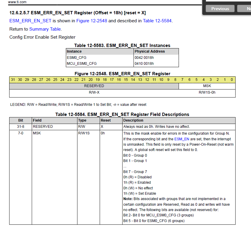
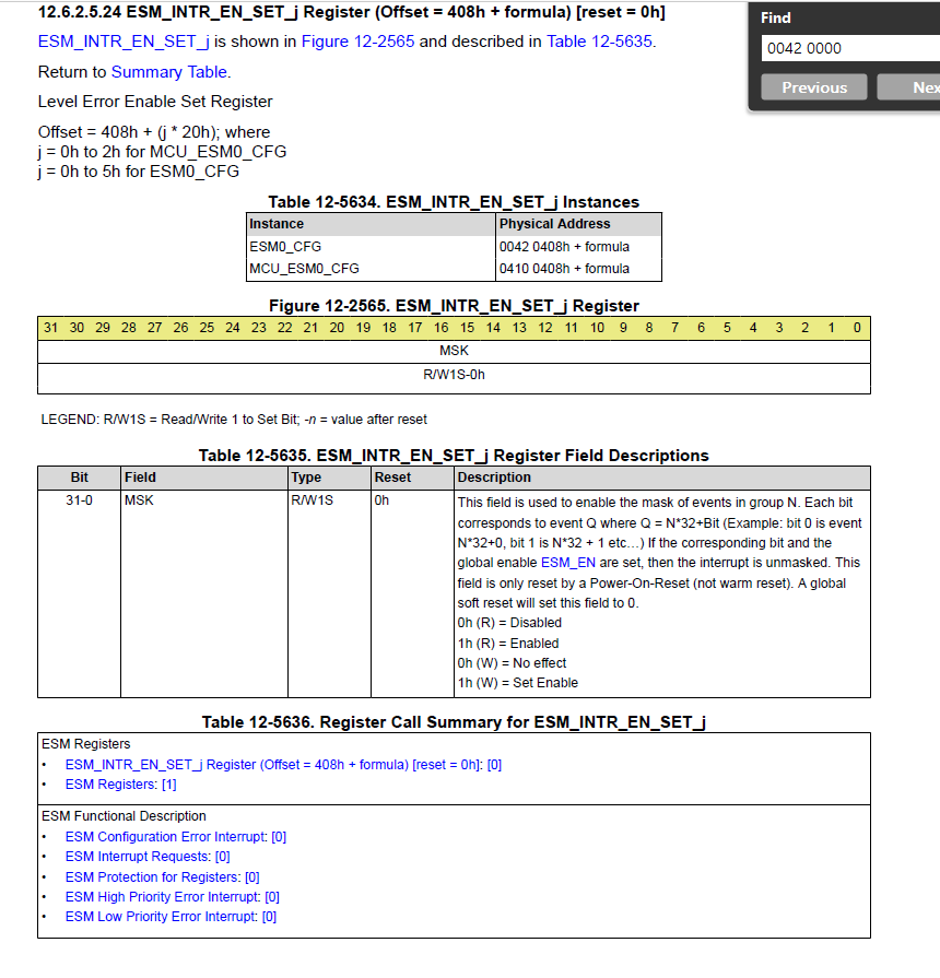
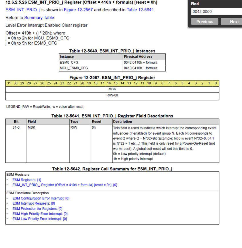
    Now, if you look at the ESM Registers, there are mainly 3 registers that you need to check .

    And I have captured these registers from AM64X TRM .

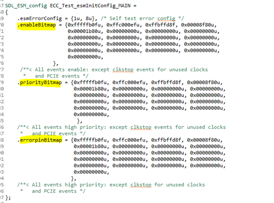
  • After reading the above information, you can see code in the bitmap configuration.

    The ESM error events are divided into groups of 32 each.So the events 0-31 in the ESM Interrupt Map Table would be in group 0, 32-63 in group 1 and so on. Each entry of the enableBitmap, priorityBitmap, errorpinBitmap structs corresponds to a particular ESM group.

    There are mainly 3-bit map fields .

    enableBitmap:

    You can check the interrupt map table from TRM and identify the event of interest. In order to enable that particular error event, you can set the bit corresponding to that event number to 1 in the enableBitmap struct.

    priorityBitmap:

    For each error event, you can set the priority of the interrupt to either High or Low. In the priorityBitmap struct, we set the interrupt priority of the enabled ESM events.In order to configure a high priority interrupt for a particular ESM event, we can set the bit corresponding to the ESM event as 1. And similarly, to configure a low priority interrupt you can set the bit to 0.

    By default the priority of all the events are set to 0. 

    errorpinBitmap : 

    In the errorpinbitmap, you can enable an external pin to monitor the status of an ESM event exteranally. You can enable an external pin by setting the bit

    corresponding to an ESM event to 1. 

  • Example: Let's say I wanted to enable the ECC aggregator for WWD_0 peripheral , and that interrupt number value is


                    (Screenshot taken from AM64X TRM)

    DMSC0_RTI_0_INTR_WWD_0 - > 5

    Priority > High

    Error Pin Event: > Disable

    The above event should come under Group 0 and so highlighted position of all bitmap fields should be configured .

    Now, you can just keep 1 value in the 5th position in Group 0.


    i.e.  .enableBitmap = {0x00000020u, 0x00000000u, 0x00000000u, 0x00000000u,
    0x00000000u, 0x00000000u, 0x00000000u, 0x00000000u,
    0x00000000u, 0x00000000u, 0x00000000u, 0x00000000u,
    0x00000000u, 0x00000000u, 0x00000000u, 0x00000000u,
    0x00000000u, 0x00000000u, 0x00000000u, 0x00000000u,
    0x00000000u,
    },

    .priorityBitmap = {0x00000020u, 0x00000000u, 0x00000000u, 0x00000000u,
    0x00000000u, 0x00000000u, 0x00000000u, 0x00000000u,
    0x00000000u, 0x00000000u, 0x00000000u, 0x00000000u,
    0x00000000u, 0x00000000u, 0x00000000u, 0x00000000u,
    0x00000000u, 0x00000000u, 0x00000000u, 0x00000000u,
    0x00000000u,
    },

    .errorpinBitmap = {0x00000000u, 0x00000000u, 0x00000000u, 0x00000000u,
    0x00000000u, 0x00000000u, 0x00000000u, 0x00000000u,
    0x00000000u, 0x00000000u, 0x00000000u, 0x00000000u,
    0x00000000u, 0x00000000u, 0x00000000u, 0x00000000u,
    0x00000000u, 0x00000000u, 0x00000000u, 0x00000000u,
    0x00000000u,
    },

  • The above explanation is the same for MCU ESM and Wakeup ESM Modules, and it is the same approach for AM64X and AM62X devices.