This thread has been locked.

If you have a related question, please click the "Ask a related question" button in the top right corner. The newly created question will be automatically linked to this question.

Double display issue with cameras using ipu vision sdk

Part Number: DRA76P

Hello,

We are using SDK v6AO.1.1, android 8.1, linux kernel 4.4.117, and vision_sdk to manage cameras.

We are not be able to have dual display and cameras working at the same time.

We just can have one android output with cameras or two outputs without them.

In our case, TV (HDMI) output as primary video output, and LCD1 output as external video.

Regarding overlays, VID2 is for cameras, VID3 for logo and VID1 and GFX for android outputs.

I’m going to talk with a specific case:

Android primary display TV → HDMI, externa display LCD1 → DVID

setprop ro.hwc.primary.conn HDMI

setprop ro.hwc.external.conn DVID

In vision_sdk, we just configure the overlays for the camera and the logo, VID2 and VID3 for the TV output.

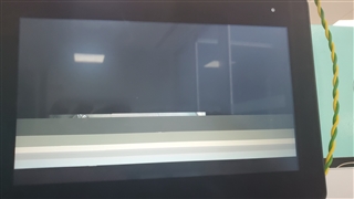
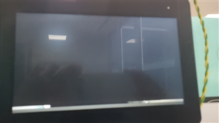
When we have the dual displays with cameras, we can see in the video output, that we have the cameras, a teared image and this trace in dmesg:

[drm:omap_crtc_error_irq] *ERROR* tv: errors: 00008000

This trace means SYNC lost in TV output.

Debugging, we found that the trigger is the setting to 1 of the register GOLCD bit, the output without cameras.

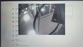
If I comment the setting of GOLCD bit in omap_crtc_atomic_flush from omap_crtc.c, in the HDMI output I have the cameras and android working perfectly but, logically, the LCD1 display shows nothing.

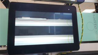
But at the moment a write manually “devmem 0x58001040 w 0x0000132B” (mask GOLCD 0x00000020), the sync lost appears, the hdmi image turns teared and the LCD diplay shows images.

I don’t know what is the problem and I don’t understand why the GO bit in the other display desyncs the other one without an overlay in common.

Any idea?

Regards,

Miguel

  • Hi Miguel,

    Due to a holiday in India, half of our team is currently out of office. Please expect a 1~2 day delay in responses.

    Apologies for the delay, and thank you for you patience.

    Regards,
    Takuma

  • no worries, thanks for the info.

  • Hi Miguel,

    Is there a possibility that same video pipeline is connected to both the outputs? Then there is possibility of tearing artifacts. 

    Also another suspect could be the common register DISPC_CONTROL1 for TV and LCD1 output. This common register enables TV output as well as LCD1 and also it contains Go bit for both of them. May be writing this from two different cores is affecting the output.. 

    Regards,

    Brijesh

  • Hi Brijesh,

    Thank you for your support.

    Is there a possibility that same video pipeline is connected to both the outputs? Then there is possibility of tearing artifacts. 

    I have modified ChainsCommon_DualDisplay_StartDisplayCtrl from vision_sdk/apps/src/rtos/usecases/common/chains_common.c and I set the LCD pipeline as follow:

    /* Configure HDMI overlay parameters */
    pVInfo->isInputPipeConnected[0] = TRUE;
    pVInfo->isInputPipeConnected[1] = TRUE;
    pVInfo->isInputPipeConnected[2] = TRUE;
    pVInfo->isInputPipeConnected[3] = TRUE;
    pVInfo->writeBackEnabledFlag = FALSE;

    /* Configure LCD overlay params */
    pVInfo->isInputPipeConnected[0] = FALSE;
    pVInfo->isInputPipeConnected[1] = FALSE;
    pVInfo->isInputPipeConnected[2] = FALSE;
    pVInfo->isInputPipeConnected[3] = FALSE;
    pVInfo->writeBackEnabledFlag = FALSE;

    And I checked in ti_hwc if the two displays are configured correctly and I get this traces:

    ti_hwc : Setting up plane 33 and connecting connector 32 to crtc 34

    ti_hwc : Setting up plane 37 and connecting connector 36 to crtc 38

    Also another suspect could be the common register DISPC_CONTROL1 for TV and LCD1 output. This common register enables TV output as well as LCD1 and also it contains Go bit for both of them. May be writing this from two different cores is affecting the output..

    The IPU2 core doesn't write LCD1GO bit. If I remove all LCD1GO writings from android, I get a blank image in the LCD1 output and the TV output is fine with android video and camera video, but If I write just one LCD1GO manually from terminal, I get image from LCD1 display but the TV display becomes teared, I can send you an image in a while.

    Regards,

    Miguel

  • Hi Miguel,

    The IPU2 core doesn't write LCD1GO bit. If I remove all LCD1GO writings from android, I get a blank image in the LCD1 output and the TV output is fine with android video and camera video, but If I write just one LCD1GO manually from terminal, I get image from LCD1 display but the TV display becomes teared, I can send you an image in a while.

    ok, in this case, can you read this register and see if the go bit is already set for TV, then can you please try keeping it enabled, instead of resetting it? 

    Regards,

    Brijesh

  • Hi Brijesh,

    I don't know if I understand correctly.

    For example:

    Removed LCD1GO bit from omap_crtc_atomic_flush, I just allow the go bit for tv.

    I play a video in tv display, then, when I try to read the register DISPC_CONTROL1, I get:

    devmem 0x58001040

    0x0000030B

    and sometimes the bit TVGO to "1", I mean:
    0x0000034B

    If I understand correctly the bit TVGO is cleared automatically.

    I play a video in LCD1 display, because no one is writing the LCD1GO the display is blank.

    then I write: devmem 0x58001040 w 0x0000036B or devmem 0x58001040 w 0x0000032B, if read the register I get: 0x0000030B or 0x0000034B. It's true that I see the two videos but at the moment I try to show the camera on the tv display, the lost appears ([drm:omap_crtc_error_irq] *ERROR* tv: errors: 00008000)

    I haven't ever seen the LCD1GO in this case.

    The code that I use to show the camera is:

                // Enable VID2 (enable DISPC_VID2_ATTRIBUTES bit 0)
                reg_value = HW_RD_FIELD32_RAW(SOC_DISPC_BASE + DSS_DISPC_VID2_ATTRIBUTES, DSS_DISPC_VID2_ATTRIBUTES_ENABLE_MASK,
                                              DSS_DISPC_VID2_ATTRIBUTES_ENABLE_SHIFT);
                if (reg_value == DSS_DISPC_VID2_ATTRIBUTES_ENABLE_VIDEODIS)
                {
                    HW_WR_FIELD32_RAW(SOC_DISPC_BASE + DSS_DISPC_VID2_ATTRIBUTES, DSS_DISPC_VID2_ATTRIBUTES_ENABLE_MASK,
                                      DSS_DISPC_VID2_ATTRIBUTES_ENABLE_SHIFT, DSS_DISPC_VID2_ATTRIBUTES_ENABLE_VIDEOENB);
                }
                break;
    

    On the other hand, the teared images are like that:

    it has a few lines of the camera

  • Hi Miguel,

    Do you mean those white lines at the end of the picture? Are they not part of the original picture? 

    If I understand correctly the bit TVGO is cleared automatically.

    Yes, as per the TRM, yes, they are cleared automatically. 

    Just wondering if TV and LCD1 can enabled simultaneously. Let me check in the TRM. 

    Regards,

    Brijesh

  • Hi Brijesh,

    I'm not sure if the white lines are part of the picture, sorry. Another pic.

    The red line is the part of the camera image. The green line points the white lines.

    Regarding if TV and LCD1 can be enabled simultaneously, we can have the two outputs working at the same time if there isn't camera.

    Regards,

    Miguel

  • Hi Miguel,

    Sorry, but where do you see tearing artifacts in the image? 

    Regarding if TV and LCD1 can be enabled simultaneously, we can have the two outputs working at the same time if there isn't camera.

    oh, in this case, what does display show? Is it some background color? Is it possible to show some known pattern in this case? 

    I just want to check if the issue is coming due to camera or this is due to simultaneous enabling of TV and LCD1. 

    Regards,

    Brijesh

  • Hi Brijesh,

    Sorry, but where do you see tearing artifacts in the image?

    My fault, I called "teared" to these lines.

    oh, in this case, what does display show? Is it some background color? Is it possible to show some known pattern in this case? 

    The two displays have whatever we want to have on them, I mean, in our case, android with 2 outputs, the primary and the external displays.

    Regards,
    Miguel

  • I guess you might still see even when camera is not connected. 

    Also i think you are using vout1 interface to connect to your external display. 

    vout1 can use any one of the LCD output using below mux. Have you considered using any other LCD, so that go bit becomes independent for LCD and TV outputs? 

    Regards,

    Brijesh

  • Hi Brijesh,

    Thank you for the idea, I didn't still test it. I'm going to test it right now.

    Regards,

    Miguel

  • Thanks Miguel, i will move this ticket to "waiting" state.

  • Hi Brijesh,

    The error is still the same, changing the vout1 to LCD2.

    Initial state:

    devmem 0x58000040 -> 0x00010001 // vout1 LCD1

    I have changed to LCD2:

    devmem 0x58000040 w 0x00020001

    devmem 0x58000040 -> 0x00020001

    Regards,

    Miguel

  • Hi Brijesh,

    Is it possible that we have a useCase file bad configured.

    We have this usecase file:

    UseCase: chains_vipSingleRvcCamCrc_Display
    
    // Camera's Layer
    IssCapture -> VPE -> Dup
    Dup -> Merge
    Dup -> Sync -> Alg_VpeSwMs -> Merge
    Merge -> Display_Video
    GrpxSrc -> Display_Grpx

    And we added manually the second display. It's true that it works without showing the camera, but we don't know, we are totally lost at this point.

  • Hi Brijesh,

    Another thing.

    If we play with the overlays, for example:

    /* Configure HDMI overlay parameters */
    pVInfo->mode = 0;
    pVInfo->isInputPipeConnected[0] = TRUE; // VIDEO 1
    pVInfo->isInputPipeConnected[1] = FALSE; // VIDEO 2 RVC
    pVInfo->isInputPipeConnected[2] = TRUE; // VIDEO 3 LOGO
    pVInfo->isInputPipeConnected[3] = TRUE; // GFX
    pVInfo->writeBackEnabledFlag = FALSE;

    /* Configure LCD overlay params */

    pVInfo->isInputPipeConnected[0] = FALSE;
    pVInfo->isInputPipeConnected[1] = TRUE; // RVC
    pVInfo->isInputPipeConnected[2] = FALSE; // LOGO
    pVInfo->isInputPipeConnected[3] = FALSE;
    pVInfo->writeBackEnabledFlag = FALSE;

    We mean, we configure the rvc overlay in the LCD1 instead HDMI, just with the example above, the behavior is the same but in the LCD display. The HDMI(tv) display is fine but the LCD display has the bad image, like the photo before posted.

    Regards,

    Miguel

  • Hi Brijesh,

    Any news regarding this issue?

    Regards,

    Miguel

  • Hi Brijesh,

    Please, could you give me some feedback? I don't know if you need something.

    I did another test in order to simplify the case. I changed the use case to a simplest one:

    IssCapture -> Display_Video

    and I still have the sync lost irq.

    How can I manage the overlays from vision_sdk and kernel? maybe I can play with that.

    Regards,

    Miguel

  • Hi Brijesh,

    I have made a progress.

    I didn't know, but a former coworker added a patch to display the splash screen or in our case the camera at early boot. He used patches from this TI post

    https://e2e.ti.com/support/processors-group/processors/f/processors-forum/722673/linux-early-splash-screen-on-using-u-boot-for-osd-panel-1920x1200-display

    I don't know why he configured the number of overlays in the kernel to 2 instead of 4.

    I removed those patches, because, for now, we don't need the early boot, and configure correctly the overlays. Currently, we have the two display with the camera working, but, testing it, I found that if we play a video in the display with the camera overlay, the multimedia video and the camera mix together, both are working but mixed.

    Example with android settings UI and the camera working

    Example with a video and the camera mixed

    In the picture doesn't appreciate correctly, but the lines in the picture is the camera (working).

    I don't see any error logs in dmesg.

    Regards,

    Miguel

  • Hi Miguel,

    Is there a possibility that same video pipeline is connected to both the displays? Then, can you please disable the pipelines from the overlays.

    In the attribute register of each video/gfx pipeline, there are two fields CHANNELOUT and CHANNELOUT2. CHANNELOUT is used to connect video pipeline to either LCD or to TV/HDMI output, where CHANNELOUT2 is used to select LCD output. Can you please check this register for all enabled video pipeline and make sure that same pipeline is not connected to two overlays/LCDs? 

    Regards,

    Brijesh

  • Hi Brijesh,

    Thank you for the answer.

    The read registers are:

    GFX ATTRIBUTES, desired output LCD1, read value: CHANNELOUT2 00, CHANNELOUT 0

    VID1 ATTRIBUTES, desired output HDMI, read value: CHANNELOUT2 00, CHANNELOUT 1

    VID2 ATTRIBUTES, desired output HDMI, read value: CHANNELOUT2 00, CHANNELOUT 1

    VID3 ATTRIBUTES, desired output HDMI, read value: CHANNELOUT2 00, CHANNELOUT 1

    As far as I know, they are correctly configured.

    The weird thing, for me, is the fact that when android displays an UI the camera and the image displayed via HDMI is ok, but when we play a movie, the movie and the camera mix together, even if we put the ENABLE bit from the VID2 ATTRIBUTES (camera overlay) register is set to 0.

    Regards,

    Miguel

  • Hi Miguel,

    But then is there a corruption in the memory? Is it possible to check the buffer which is going to the Video pipeline? 

    Maybe, while playing the movie, you can half the CPU, get the buffer address from the BA register of this pipeline and dump the buffer to see if it contains correct content? If the buffer content is incorrect, or merged/corrupted, it is not DSS issue. 

    Or if you just want to display movie, can you disable other pipeline to the same overlay and see if it works fine? 

    Regards,

    Brijesh 

  • Hi Brijesh,

    Thanks for your support. I fixed the issue, basically, the problem was in the hardware composer, I don't know yet which is exactly the problem, but I fixed it hardcoding the number of overlays to 2.

    In conclusion, to fix the issue, I removed the early boot patch and I hardcoded the number of overlays in hardware composer to 2.

    Regards,

    Miguel