Other Parts Discussed in Thread: AM6422, SK-AM64B, SK-AM62A-LP, DP83867IR
Tool/software:

This thread has been locked.
If you have a related question, please click the "Ask a related question" button in the top right corner. The newly created question will be automatically linked to this question.
Tool/software:
Hello Vaibhav,
Thank you for the query.
Let me check with the device expert and get his inputs.
Regards,
Sreenivasa
Hello Vaibhav,
Please refer below inputs i received from the expert. Are you able to isolate the TX signals from the MAC to the EPHY and perform a quick test.
All of the referenced signals use the same IO buffer. (FYI, PRU uses the buffer in a horizontal configuration rather than vertical, but I would not expect this to make a difference.) The customer reports the same issue for both CPSW and PRU so this expectation holds. Drive strength would also be the same (unless they have changed it) as we only support one (default). I will assume they haven’t done something different like set only the affected pins at a different IO voltage…
As this issue is seen on only a small subset of pins, and this subset is identical for all 3 interfaces, my initial assumption would be that the PHY loading for these pins is different. This assumes the relative implementations for all the PHYs is the same of course. The DS for the PHY they are using indicates a max input capacitance of 5pF “for all specifications” with no documented minimum. Might be worth them asking the PHY team if these pins present more loading than the others. Depending on their schematic, they could also disconnect several signals from the PHY and observe the relative change in RT/FT. See if these two pins behave differently.
Regards,
Sreenivasa
Dear Sreenivasa,
Thanks a lot for response.
1)
my initial assumption would be that the PHY loading for these pins is different. This assumes the relative implementations for all the PHYs is the same of course. The DS for the PHY they are using indicates a max input capacitance of 5pF “for all specifications” with no documented minimum. Might be worth them asking the PHY team if these pins present more loading than the others.
We believe TI have strong internal collaboration, So Could you (TI) check with PHY team and confirm whether TX_D0 & TX_D1 have different loading than other pins or not?
2) We believe TI should have test verification/validation data of AM64xx SOC with PHY (DP83867IRRGZ), as it is used in EVM of TI. So could you please check in test report and confirm rise/fall time is same for all TX signals or TX_D0 & TX_D1 rise/fall time is less compare to other TX signals?
-
Vaibhav
Hello Vaibhav,
Thank you.
We believe TI have strong internal collaboration, So Could you (TI) check with PHY team and confirm whether TX_D0 & TX_D1 have different loading than other pins or not?
I do not understand what you meant by strong collaboration. The EPHY is a different PL.
I can start a new thread internally to check with the Ethernet PL. Please expect delay in response.
2) We believe TI should have test verification/validation data of AM64xx SOC with PHY (DP83867IRRGZ), as it is used in EVM of TI. So could you please check in test report and confirm rise/fall time is same for all TX signals or TX_D0 & TX_D1 rise/fall time is less compare to other TX signals?
This has been timing closed. This is part of the internal validation.
Regards,
Sreenivasa
Hello Vaibhav,
Can you please confirm the observations are for the below project.
500-00011_EMS_Linux-SBC Board SCH-variant
Regards,
Sreenivasa
Hello Vaibhav,
Thank you.
Let me check with the EPHY team.
Are you able to isolate the series resistor and test.
Regards,
Sreenivasa
Dear Sreenivasa,
We Isolated RGMII TX_D1 & TX_D2 between the EPHY & AM6422 by removing the series resistor and loaded them with AM6422 pin capacitance + trace capacitance + external 5pF capacitor, we do not observe significant difference in TX_D1 & TX_D2 rise/fall time, it was close to the 0.75ns as expected.
However, if EPHY (DP83867IRRGZ) is connected with AM6422 at that time around 1.2ns rise & fall time obseved for TX_D0 & TX_D1 signal. This is weird, Seems loding on TX_D0 & TX_D1 pin of DP83867IRRGZ is higher than 5pF.
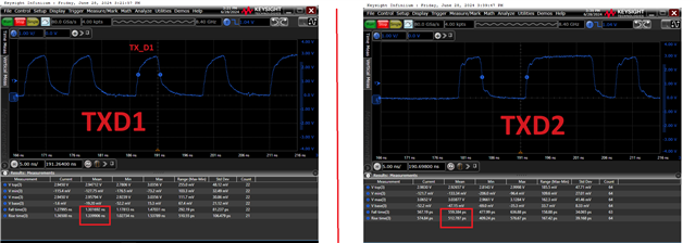
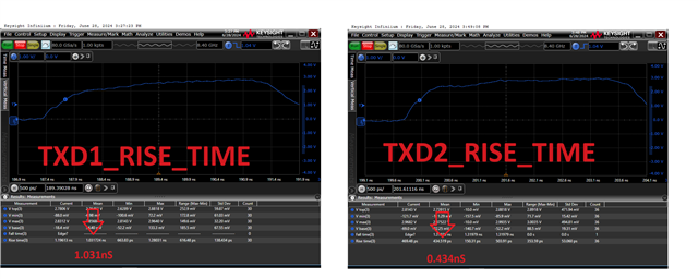
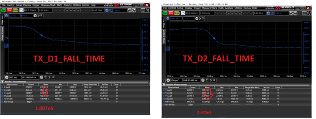
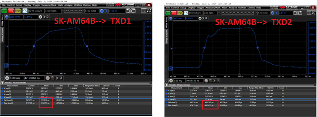
While capturing the RGMII signal of all 3-interface channels. We observed around 1.2ns rise & fall time for TX_D0 & TX_D1 signal, which is violating the rise & fall time limit. TX_CLK, TX_D2 & TX_D3 signal rise & fall time is closer the 0.75nS and better then TX_D0 & TX_D1.
To double confirm the observation, We swaped the TX_D1 & TX_D2 connection ( Connected TX_D1 pin of SOC with TX_D2 pin of EPHY & Connected TX_D2 pin of SOC with TX_D1 pin of EPHY) and observed acceptable rise/fall (~0.75) time on TX_D2 pin of EPHY, However higher rise/fall (~1.2) time on TX_D1 pin of EPHY.
We believe loading on the TX_D0 & TX_D1 signal is higher then other TX_CLK, TX_D2 & TX_D3 signal.
Let me check with the EPHY team.
Do you have any feedback from EPHY team?
-
Best regards
Vaibhav
Hello Vaibhav,
Thank you for the support and appreciated.
We have neem discussing with the EPHY team but i do not have any conclusive data to share.
I will share this information with the EPHY team and ask for their inputs.
Regards,
Sreenivasa
Hello Vaibhav,
Quick question
Did you observed any communication issues with the waveforms you have been measuring.
Regards,
Sreenivasa
Hello Vaibhav,
Please refer below inputs from the EPHY team:
We understand the data collected. We are trying to understand the setup, but we are looking to isolate the PHY from the traces. Internally, our hypothesis is either the PHY is loading as customer is thinking, or the board traces are loading by introducing extra parasitics compared to TX_D0 and D1.
Typically, these series resistors are closer to the driver; thus it is farther from the input of the PHY pin which is where the key care-about is. Can you confirm that customer is measuring these waveforms at the PHY pin?
We suggest the following to isolate board from PHY.
Experiment:
- Customer can look to power off PHY or even remove PHY from board and remeasure the rise and fall time relative to TX_D0/1. If the setup/hold time is still at 1.2ns, this looks to be an issue on the board design and will need to be debugged. If time is drastically different, we can look to check this with design team.
Regards,
Sreenivasa
Dear Sreenivasa,
PLease refer below answer of your question.
Did you observed any communication issues with the waveforms you have been measuring.
-> Yes, Communication is working.
Typically, these series resistors are closer to the driver; thus it is farther from the input of the PHY pin which is where the key care-about is. Can you confirm that customer is measuring these waveforms at the PHY pin?
--> Confirmed, Observation is on the exact pin of PHY.
Customer can look to power off PHY or even remove PHY from board and remeasure the rise and fall time relative to TX_D0/1. If the setup/hold time is still at 1.2ns, this looks to be an issue on the board design and will need to be debugged. If time is drastically different, we can look to check this with design team.
--> (1) Power Off the PHY and measure the rise/fall time at pin of PHY, Does not create real & good test setup to understand the issue. As certain amount of capacitance/loading could be provided by PHY pin during power off condition.
We suggest the following to isolate board from PHY.
board traces are loading by introducing extra parasitics compared to TX_D0 and D1.
--> Impedance control trace length of TX_D0 and D1 is similar to other TX_CLK, TX_D2 & TX_D3 signals, My hypothesis is parasitics capacitance remain almost similar in this scenario. Correct me if I am wrong.
remove PHY from board and remeasure the rise and fall time relative to TX_D0/1
-> Due to limitations of placement and BGA package of AM64, Series resistors are not placed closed to the AM64, it is in between AM64 & EPHY. if rise/fall time of TX_D0 and D1 is less at series resistors then it is not going to improve at PHY pin, and we have already shared the observation at series resistor in previous feedback.
We Isolated RGMII TX_D1 & TX_D2 between the EPHY & AM6422 by removing the series resistor and loaded them with AM6422 pin capacitance + trace capacitance + external 5pF capacitor, we do not observe significant difference in TX_D1 & TX_D2 rise/fall time, it was close to the 0.75ns as expected.
If the setup/hold time is still at 1.2ns, this looks to be an issue on the board design and will need to be debugged.
--> Just i have small correction in this statement, here we are discussing about the rise/fall time, not setup/hold time.
If time is drastically different, we can look to check this with design team.
We have observed significant difference in rise/fall time of TX_D0 & TX_D1 compared to TX_CLK, TX_D2 & TX_D3. we recommend to check rise/fall time at TI end and confirm rise/fall time of TX_D0 & TX_D1 is above 0.75nS or not? if rise/fall time of TX_D0 & TX_D1 is above then what are the solution available with TI.
-
Vaibhav
Hello Vaibhav,
Thank you for the detailed inputs. Appreciated.
Let me check with the EPHY team and update you.
Regards,
Sreenivasa
Hello Vaibhav,
The EPHY team believes they could get some information if the testing is done with the EPHY off.
Could you isolate the ferrites for one of the EPHY and do a measurement.
Thank you for the support.
Regards,
Sreenivasa
Hello Vaibhav,
The EPHY team confirmed that they would want to measure the timing by disabling all the EPHY supplies.
Regards,
Sreenivasa
Dear Sreenivasa,
Sure, I will test TX signal rise/fall time during the power-off condition of EPHY, and update you on my observation.
please note, according to my understanding this is EPHY (DP83867IRRGZ ) issue either design or specific production bench of DP83867IRRGZ, Idealy loading of all TX data signal (TX_D0, TX_D1, TX_D2, TX_D3) should be simailar.
So it would be great if EPHY team verify the rise/fall time (loading of EPHY) at there end on TI EVM at least one time. This approach will be helpful to double confirm the observation is similar at both end or not?
Since 2 weeks, we do not have conclusive answer on the below question, Did you get any conclusive feedback from EPHY team?
Could you (TI) check with PHY team and confirm whether TX_D0 & TX_D1 have different loading than other pins or not?
-
Vaibhav
Hello Vaibhav,
Thank you for supporting the debug. Sincerely appreciated.
Here are some additional queries i received:
We would like to understand how the PHY is operating in RGMII mode and if there are any other settings which may affect this behavior. Can customer confirm if they are strapping into (and not further manipulating RGMII registers), or if customer is going into RGMII via registers to begin with.
If latter option, can they provide the following register values:
Reg 0x10, 0x32, 0x33, 0x37, 0xD3, 0x6E, 0x6F
Please note that the latter six registers are extended registers and thus need extended access to get appropriate values.
We would also request that customer provide waveforms of the 1.2ns and near-0.75ns signals as well as confirm that their design conforms to our schematic and layout checklist located in our product folder.
ince 2 weeks, we do not have conclusive answer on the below question, Did you get any conclusive feedback from EPHY team?
Could you (TI) check with PHY team and confirm whether TX_D0 & TX_D1 have different loading than other pins or not?
The initial reply was there is no difference. We have requested the EPHY team to do some additional analysis to root cause possible issue.
Regards,
Sreenivasa
Dear Sreenivasa,
The EPHY team confirmed that they would want to measure the timing by disabling all the EPHY supplies.
I checked, RGMII TX not started without power supplies of EPHY. We believe RGMII communication start after clock & successful communication with EPHY on the MDIO.
Please check from your end, Such kind test is possible & TI has performed such kind test earlier. if yes then please provide the procedure/steps.
-
Vaibhav
Hello Vaibhav,
Thank you.
The simplest way is to do an MII loopback.
Have you had a chance to perform MII loopback testing before?
Regards,
Sreenivasa
Dear Sreenivasa
I do not tested MII loopback earlier. For you kind information MII loopback is possible if PHY is power ON!
-
Vaibhav
Hello Vaibhav,
Thank you.
Please note that MII loopback is MAC initiated testing. You can always send data but you will never receive any data and will result in loopback failure.
Regards,
Sreenivasa
Dear Sreenivasa,
Could you (TI) check with PHY team and confirm whether TX_D0 & TX_D1 have different loading than other pins or not?The initial reply was there is no difference. We have requested the EPHY team to do some additional analysis to root cause possible issue.
Below requested waveform clearly represent that loading on the TX_D1 is more compared to other (TX_D2) signal. Common test method is used for the same.
--> Below is the rise/fall time waveforms of TX_D1_5ns_H_Scale.zip & TX_D2_5ns_H_Scale.zip at 5nS Horizontal scale.
--> Below is the rise time waveform for TX_D1_0.5ns_Rise.zip & TX_D2_0.5ns_rise.zip at 0.5nS horizontal scale.
--> Below is the falltime waveform for TX_D1_0.5ns_fall.zip & TX_D2_0.5ns_fall.zip at 0.5nS horizontal scale.
At 0.5nS horizontal scale rise time & fall time of TX_D1 is ~1nS, which is violating the 0.75nS limit.
We would like to understand how the PHY is operating in RGMII mode and if there are any other settings which may affect this behavior. Can customer confirm if they are strapping into (and not further manipulating RGMII registers), or if customer is going into RGMII via registers to begin with.
If latter option, can they provide the following register values:
Reg 0x10, 0x32, 0x33, 0x37, 0xD3, 0x6E, 0x6F
please review the below requested registers details, and confirm RGMII operation is correct or not?
Register name | Register Address | Register Value |
PHY Control Register (PHYCR) | 0x0010 | 0x5048 |
RGMII Control Register (RGMIICTL) | 0x0032 | 0x00d1 |
RGMII Control Register 2 (RGMIICTL2) | 0x0033 | 0x0000 |
Details not provided in datasheet | 0x0037 | 0x0000 |
Details not provided in datasheet | 0x00D3 | 0x0000 |
Strap Configuration Status Register 1 (STRAP_STS1) | 0x006E | 0x0001 |
Strap Configuration Status Register 2 (STRAP_STS2) | 0x006F | 0x0140 |
confirm that their design conforms to our schematic and layout checklist located in our product folder
--> Confirmed, Checklist & TI EVM reference design is followed in the custom design, Also custom design schematic is reviewed by TI.
-
Vaibhav Kundariya
Dear Sreenivasa,
Just for your information rise/fall time is based on 20% to 80% (not 10% to 90%).
-
Vaibhav
Hello Vaibhav,
Thank you for the inputs and support.
I have provided the inputs to the EPHY team and waiting for them to review and respons.
Regards,
Sreenivasa
Dear Sreenivasa,
Just for your reference, We have observed similar(less) rise/fall time on TX_D0 & TX_D1 in the TI EVM kit # SK-AM64B. if you want to see at your (TI) side then you can check.
-
Vaibhav
Dear Sreenivasa,
We have also checked the rise/fall time of TX_Data signals in the TI EVM kit # SK-AM62A-LP and observed less rise/fall time on TX_D0 & TX_D1. you can also double confirm same issue in TI EVM kit # SK-AM62A-LP.
-
Vaibhav
Hello Vaibhav,
Thank you for the measurements.
Can you please confirm all of the boards have the DP83867IR part numbers?
Regards,
Sreenivasa
Hello Vaibhav,
Thank you for all your support.
I have provided my inputs to the EPHY design team.
The reason on the IR question can be understood if you compare with the CS or IS EPHY data sheet.
Regards,
Sreenivasa