This thread has been locked.

If you have a related question, please click the "Ask a related question" button in the top right corner. The newly created question will be automatically linked to this question.

PROCESSOR-SDK-AM335X: How to configure SPI master/slave mode with SDK9

Part Number: PROCESSOR-SDK-AM335X
Other Parts Discussed in Thread: AM3351

Tool/software:

The documentation for the am335x SDK v9 states both SPI slave mode is supported and is not supported. Is SPI slave mode supported with DMA enabled?

Features Not Supported
Below contains a list of features not supported by the Linux driver. Note this isn’t meant to be an exhaustive list and only takes into account features the SPI peripheral in the SoC is capable of but is currently not supported in the Linux driver.

  • SPI slave mode is supported only with DMA enabled.

  • SPI slave mode isn’t supported.

In am33xx-l4.dtsi, we find SPI0 and SPI1 nodes,

		target-module@30000 {			/* 0x48030000, ap 77 08.0 */
			compatible = "ti,sysc-omap2", "ti,sysc";
			reg = <0x30000 0x4>,
			      <0x30110 0x4>,
			      <0x30114 0x4>;
			reg-names = "rev", "sysc", "syss";
			ti,sysc-mask = <(SYSC_OMAP2_CLOCKACTIVITY |
					 SYSC_OMAP2_SOFTRESET |
					 SYSC_OMAP2_AUTOIDLE)>;
			ti,sysc-sidle = <SYSC_IDLE_FORCE>,
					<SYSC_IDLE_NO>,
					<SYSC_IDLE_SMART>;
			ti,syss-mask = <1>;
			/* Domains (P, C): per_pwrdm, l4ls_clkdm */
			clocks = <&l4ls_clkctrl AM3_L4LS_SPI0_CLKCTRL 0>;
			clock-names = "fck";
			#address-cells = <1>;
			#size-cells = <1>;
			ranges = <0x0 0x30000 0x1000>;

			spi0: spi@0 {
				compatible = "ti,omap4-mcspi";
				#address-cells = <1>;
				#size-cells = <0>;
				reg = <0x0 0x400>;
				interrupts = <65>;
				ti,spi-num-cs = <2>;
				dmas = <&edma 16 0
					&edma 17 0
					&edma 18 0
					&edma 19 0>;
				dma-names = "tx0", "rx0", "tx1", "rx1";
				status = "disabled";
			};
		};
		
		target-module@a0000 {			/* 0x481a0000, ap 79 24.0 */
			compatible = "ti,sysc-omap2", "ti,sysc";
			reg = <0xa0000 0x4>,
			      <0xa0110 0x4>,
			      <0xa0114 0x4>;
			reg-names = "rev", "sysc", "syss";
			ti,sysc-mask = <(SYSC_OMAP2_CLOCKACTIVITY |
					 SYSC_OMAP2_SOFTRESET |
					 SYSC_OMAP2_AUTOIDLE)>;
			ti,sysc-sidle = <SYSC_IDLE_FORCE>,
					<SYSC_IDLE_NO>,
					<SYSC_IDLE_SMART>;
			ti,syss-mask = <1>;
			/* Domains (P, C): per_pwrdm, l4ls_clkdm */
			clocks = <&l4ls_clkctrl AM3_L4LS_SPI1_CLKCTRL 0>;
			clock-names = "fck";
			#address-cells = <1>;
			#size-cells = <1>;
			ranges = <0x0 0xa0000 0x1000>;

			spi1: spi@0 {
				compatible = "ti,omap4-mcspi";
				#address-cells = <1>;
				#size-cells = <0>;
				reg = <0x0 0x400>;
				interrupts = <125>;
				ti,spi-num-cs = <2>;
				dmas = <&edma 42 0
					&edma 43 0
					&edma 44 0
					&edma 45 0>;
				dma-names = "tx0", "rx0", "tx1", "rx1";
				status = "disabled";
			};
		};

Assuming slave mode is supported, can you provide example device tree nodes for both Master on SPI1 and Slave on SPI0 with DMA enabled?  Most of the SPI-related threads pre-date SDK9.

This is what I have so far for SPI0 and SPI1 in the dts.

&spi0 {
	status = "okay";
	pinctrl-names = "default";
	pinctrl-0 = <&spi0_pins>;
	ti,pindir-d0-out-d1-in = <1>;

	spislave@0 { /* Define a SPI device at chip select 0 in slave mode */
			compatible = "spislave"; /* Use the generic SPI slave-mode driver */
			spi-max-frequency = <32000000>; /* Set max SPI clock speed to 16MHz */
  		    spi-cpha;
			reg = <0>; /* Chip select 0 */
			spi-slave; /* Enable slave mode */
	};
};

&spi1 {
	status = "okay";
	pinctrl-names = "default";
	pinctrl-0 = <&spi1_pins>;

	spimaster@0 { /* Define a SPI device at chip select 0 */
			compatible = "spidev"; /* Use the generic SPI user-mode driver */
			spi-max-frequency = <16000000>; /* Set max SPI clock speed to 16MHz */
            spi-cpha;
			reg = <0>; /* Chip select 0 */
	};

The SPI related kernel configs are:
CONFIG_SPI_OMAP24XX=m
CONFIG_SPI_SPIDEV=m
CONFIG_SPI_SLAVE=y

After a reboot I add the drivers without errors and can see they have loaded, but there are no spi devices in /dev.
# modprobe spi_omap2_mcspi
# modprobe spidev
# lsmod
Module                  Size  Used by
spidev                 20480  0
spi_omap2_mcspi        24576  0
omap_sham              28672  0
omap_aes_driver        24576  0
omap_crypto            16384  1 omap_aes_driver
crypto_engine          20480  2 omap_aes_driver,omap_sham
omap_wdt               16384  0
rtc_omap               20480  1
wkup_m3_ipc            16384  0
wkup_m3_rproc          16384  1
Are the nodes in the device tree correct?
  • Hi,

    Our expert is currently out of office, please expect delays in response.

    Regards,
    Krunal

  • Hi Krunal,
    Thank you for the notice. I will continue to update this thread as I work through this.

    There is a related thread HERE when we started to port the working code from SDK7 to SDK8. We stopped to wait for SDK9. In reference to that thread, we were using a custom driver at the time b/c SPI Slave mode was not supported, thus the compatible = "slave,bf548" in the dts SPI nodes. With slave mode now supported in the SDK9 OMAP2 SPI driver, our preference is to use that. And so here we go .....

    I've made further progress (I believe) by changing the dts nodes as follows:

    &spi0 {
    	status = "okay";
    	pinctrl-names = "default";
    	pinctrl-0 = <&spi0_pins>;
    	ti,pindir-d0-out-d1-in = <1>;
    
    	slave@0 { /* Define a SPI device at chip select 0 */
        compatible = "rohm,dh2228fv";
    		spi-max-frequency = <32000000>; /* Set max SPI clock speed to 32MHz */
    		spi-cpha;
    		reg = <0>; /* Chip select 0 */
    		spi-slave; /* Enable slave mode */
    	};
    };
    
    &spi1 {
    	status = "okay";
    	pinctrl-names = "default";
    	pinctrl-0 = <&spi1_pins>;
    
           master@0 {
                    compatible = "rohm,dh2228fv";
                    spi-max-frequency = <16000000>;
                    reg = <0>;
    								spi-cpha;
            };
    };

      I now see a kernel message as the driver loads, the spidev module is loads automatically and there are two spi devices in /dev. 

    [   12.951263] spi spi0.0: setup: speed 24000000, sample trailing edge, clk normal
    [   13.049742] spi spi1.0: setup: speed 16000000, sample trailing edge, clk normal
    [...]
    
    # lsmod | grep spi
    Module                  Size  Used by
    spidev                 20480  0
    spi_omap2_mcspi        24576  0
    
    # ls /dev/spi*
    /dev/spidev0.0  /dev/spidev1.0

    I'll update here as I try the existing application against the SDK9 drivers ....

  • Using spidev_test from the SDK9 tools/spi, I get the following.

    # ./spidev_test -D /dev/spidev0.0 -v
    spi mode: 0x0
    bits per word: 8
    max speed: 500000 Hz (500 kHz)
    TX | FF FF FF FF FF FF 40 00 00 00 00 95 FF FF FF FF FF FF FF FF FF FF FF FF FF FF FF FF FF FF F0 0D  |......@.........................|
    RX | 00 00 00 00 00 00 00 00 00 00 00 00 00 00 00 00 00 00 00 00 00 00 00 00 00 00 00 00 00 00 00 00  |................................|
    
    # ./spidev_test -D /dev/spidev1.0 -v
    spi mode: 0x0
    bits per word: 8
    max speed: 500000 Hz (500 kHz)
    TX | FF FF FF FF FF FF 40 00 00 00 00 95 FF FF FF FF FF FF FF FF FF FF FF FF FF FF FF FF FF FF F0 0D  |......@.........................|
    RX | 01 01 01 01 01 01 01 01 01 01 01 01 01 01 01 01 01 01 01 01 01 01 01 01 01 01 01 01 01 01 01 01  |................................|
    

    If I'm interpreting the spi mode correctly, they should be different since SPI0 is configured with spi-slave in the dts. Also the max speed is not what is in the dts node. So, I'm not convinced SPI is working yet, especially since our existing application is having trouble writing over SPI. Since I cannot connect MOSO to MISO for a loopback test, is there another way to test SPI short of connecting a scope?

  • This is assigned to me and I'm currently out of the office but just some quick pointers here to hopefully help you move along:

    1) Try adding the spi-slave DTS property to the controller node (spi0 here), not the actual slave device definition.

    2) The max speed/actual speed may be constrained by the clock source feeding the SPI peripheral module, and the fact that it can only use an integer divider internally to achieve the requested speed. So in some cases the actual speed will be different (slower) than what's configured. What speed were you trying to configure and what did you measure?

    Regards, Andreas

  • Hi Andreas,
    Understood; thanks for letting me know you're on this.

    I corrected an incorrect link above when we started down this path last year using SDK8 with you, but we aborted to wait for SDK9. It explains how we use SPI0 (slave) and SPI1 (master). am3351-linux-support-for-spi-as-a-slave-device

    Moving spi-slave up to the controller node yields an error on dts compile:
      DTC     arch/arm/boot/dts/am335x-ct-apache.dtb
    arch/arm/boot/dts/am33xx-l4.dtsi:1728.16-1741.6: Warning (spi_bus_bridge): /ocp/interconnect@48000000/segment@100000/target-module@a0000/spi@0: incorrect #address-cells for SPI bus
      also defined at arch/arm/boot/dts/am335x-ct-gen2-common.dtsi:347.7-360.3
    arch/arm/boot/dts/am335x-ct-apache.dtb: Warning (spi_bus_reg): Failed prerequisite 'spi_bus_bridge'

    Also, my original interpretation of the "spi mode" as reported from spidev_test is incorrect. I believe it refers to modes 1-4, not master/slave, where
    Mode 0 (CPOL=0, CPHA=0)
    Mode 1 (CPOL=0, CPHA=1)
    Mode 2 (CPOL=1, CPHA=0)
    Mode 3 (CPOL=1, CPHA=1)
    But setting spi-cpha in either the controller or child node does not affect the spi mode; it is always 0x0. I've also tried spi-cpha=<1> at the controller and device levels without any effect on the mode.

    WRT our legacy application, it "seems" to be able to send data over SPI1 (master), at least the write(fd) returns the expected number of bytes written and does not return -1 or set errno. This succeeds intermittently. After sending everything, it expects to receive a request on SPI1 (slave) from the other device but fails to receive the request. I don't believe SPI0 is correctly configured in slave mode yet.

  • RE: Setting the SPI Mode
    The settings (spi-cpha and/or spi-cpol) must go in the device definition. Using spi-cpha and/or spi-cpol in the controller node has no effect. The kernel log shows the mode during boot when the driver is loaded. As a test, I set SPI0.slave (spi-cpha), SPI1.master (spi-cpha and spi-cpol) in the dts and we see the effect below.

    [ 12.609943] spi spi0.0: setup: speed 24000000, sample leading edge, clk normal
    [ 12.749822] spi spi1.0: setup: speed 16000000, sample trailing edge, clk inverted

    As for what spidev_test reports ... Looking at the source, we see spidev_test SET the SPI mode upon start-up. If you don't specify '--cpha' and/or '--cpol', it sets the mode (correctly) to Mode 0. I added a query-only option yielding the following after boot-up. It shows exactly what we expect from the nodes in the dts.
    # spidev_test -D /dev/spidev0.0 -q
    Current state of /dev/spidev0.0: spi mode 0x1 (sample trailing edge, clk normal), 8 bits per word, set to 32000000 Hz max
    # spidev_test -D /dev/spidev1.0 -q
    Current state of /dev/spidev1.0: spi mode 0x1 (sample trailing edge, clk normal), 8 bits per word, set to 16000000 Hz max

    Below are my current dts nodes for SPI0 and SPI1:

    &spi0 {
    	status = "okay";
    	pinctrl-names = "default";
    	pinctrl-0 = <&spi0_pins>;
    	ti,pindir-d0-out-d1-in = <1>;
    	spi-slave; /* Enable slave mode */
    	
    	slave@0 { 	/* Define a SPI device at chip select 0 */
    		compatible = "rohm,dh2228fv";
    		spi-max-frequency = <32000000>; /* Set max SPI clock speed to 32MHz */
    	/*	reg = <0>; /* Chip select 0 */
    		spi-cpha; 	/* SPI Mode 1 (CPOL=0, CPHA=1) */
    	};
    };
    
    &spi1 {
    	status = "okay";
    	pinctrl-names = "default";
    	pinctrl-0 = <&spi1_pins>;
    
    	master@0 {
    		compatible = "rohm,dh2228fv";
    		spi-max-frequency = <16000000>;
    		reg = <0>;
    		spi-cpha; 	/* SPI Mode 1 (CPOL=0, CPHA=1) */
    	};
    };

    So, I believe the mode and speed are configured correctly. I'll reply separately on the SPI0 Slave status.

  • RE: SPI0 Slave status

    I added some debug logic to spi-omap2-mcspi.c:omap2_mcspi_setup_transfer() to print the Master/Slave status of each device.
    if (spi_controller_is_slave(spi->controller)) {
    	dev_info(&spi->dev, "is a SLAVE\n");
    } else {
    	dev_info(&spi->dev, "is a MASTER\n");
    }
      
    And we see SPI0 is still a Master with spi-slave in the slave device dts configuration.
    [  706.295806] spi spi0.0: setup: speed 24000000, sample trailing edge, clk normal
    [  706.304657] spi spi0.0: is a MASTER (spi->controller->slave=0, spi->master->slave=0)
    [  706.336865] spi spi1.0: setup: speed 16000000, sample trailing edge, clk normal
    [  706.344277] spi spi1.0: is a MASTER (spi->controller->slave=0, spi->master->slave=0)
    ... and since spi_controller_is_slave() checks for CONFIG_SPI_SLAVE, I've verified this is set in the kernel .config file:
    $ grep CONFIG_SPI_SLAVE .config
    CONFIG_SPI_SLAVE=y
    CONFIG_SPI_SLAVE_TIME=y
    CONFIG_SPI_SLAVE_SYSTEM_CONTROL=y
     
    If spi-slave needs to be in the controller node, what else is needed in the controller to make #address-cells happy?
  • Hi Glen,

    Try adding the spi-slave DTS property to the controller node (spi0 here), not the actual slave device definition.

    Did you try the above suggestion? The latest DTS you posted still has this at the incorrect place.

    Also I'll be out of the office for the next two days so responses will be delayed.

    Regards, Andreas

  • Hi Andreas,

    Yes, I tried moving spi-slave up to the controller node, but then the DTS fails to compile:

    DTC arch/arm/boot/dts/am335x-ct-apache.dtb
    arch/arm/boot/dts/am33xx-l4.dtsi:1728.16-1741.6: Warning (spi_bus_bridge): /ocp/interconnect@48000000/segment@100000/target-module@a0000/spi@0: incorrect #address-cells for SPI bus
    also defined at arch/arm/boot/dts/am335x-ct-gen2-common.dtsi:347.7-360.3
    arch/arm/boot/dts/am335x-ct-apache.dtb: Warning (spi_bus_reg): Failed prerequisite 'spi_bus_bridge'

    where SPI0 is

    &spi0 {
    	status = "okay";
    	pinctrl-names = "default";
    	pinctrl-0 = <&spi0_pins>;
    	ti,pindir-d0-out-d1-in = <1>;
    	spi-slave; /* Enable slave mode */
    	
    	slave@0 { 	/* Define a SPI device at chip select 0 */
    		compatible = "rohm,dh2228fv";
    		spi-max-frequency = <32000000>; /* Set max SPI clock speed to 32MHz */
    		reg = <0>; /* Chip select 0 */
    		spi-cpha; 	/* SPI Mode 1 (CPOL=0, CPHA=1) */
    	};
    };

  • Hi,

    Andreas will be out of office for next couple of days and please expect delays in responses.

    Regards,
    Krunal

  • I added "#address-cells = <0>;" and removed "reg = <0>" on the controller node, and the DTS compiles successfully. I now see SPI0 configured in slave mode:

    # journalctl |grep spi
    Aug 12 17:00:14 1530163d kernel: spi spi0.0: setup: speed 48000000, sample trailing edge, clk normal
    Aug 12 17:00:14 1530163d kernel: spi spi0.0: is a SLAVE (spi->controller->slave=1, spi->master->slave=1)
    Aug 12 17:00:14 1530163d kernel: spi spi1.0: setup: speed 16000000, sample trailing edge, clk normal
    Aug 12 17:00:14 1530163d kernel: spi spi1.0: is a MASTER (spi->controller->slave=0, spi->master->slave=0)

    Please review and comment if you are in agreement that "#address-cells = <0>;" is what is required. 

    The current spi0 DTS slave node is:

    &spi0 {
    	status = "okay";
    	pinctrl-names = "default";
    	pinctrl-0 = <&spi0_pins>;
    	ti,pindir-d0-out-d1-in = <1>;
    	#address-cells = <0>;
    	spi-slave;
    
    	slave@0 { 	/* Define a SPI device at chip select 0 */
    		compatible = "rohm,dh2228fv";
    		spi-max-frequency = <16000000>; /* Set max SPI clock speed to 16MHz */
    		spi-cpha; 	/* SPI Mode 1 (CPOL=0, CPHA=1) */
    	};
    };

    At this point I'd hoped (optimistically) the existing application would run, but it doesn't. The first thing the main app does is send a "boot loader" over SPI1 to a DSP. The DSP sends a message back over SPI0 that the boot loader is starting. The main app never sees a message on SPI1. I do have the advantage of the board running under the old SDK and Linux kernel 4.14, and so I thought I'd compare the devices in /sys/devices/platform/ocp, but they are so vastly different; I suppose that is because of the evolution of the am33xx-l4.dtsi device tree.

    I did find the spi devices at

    # spi0
    ocp/48000000.interconnect/48000000.interconnect:segment@0/48030000.target-module/48030000.spi# ls
    dma:rx0                            dma:tx1                            modalias                           spi_slave                          uevent
    dma:rx1                            driver                             of_node                            subsystem
    dma:tx0                            driver_override                    power                              supplier:platform:44e10800.pinmux
    
    # where spidev0.0 is found at
    ocp/48000000.interconnect/48000000.interconnect:segment@0/48030000.target-module/48030000.spi/spi_slave/spi0/spi0.0/spidev/spidev0.0
    
    # and spi1
    ocp/48000000.interconnect/48000000.interconnect:segment@100000/481a0000.target-module/481a0000.spi# ls
    dma:rx0                            dma:tx1                            modalias                           spi_master                         uevent
    dma:rx1                            driver                             of_node                            subsystem
    dma:tx0                            driver_override                    power                              supplier:platform:44e10800.pinmux
    
    # where spidev1.0 is found at
    ocp/48000000.interconnect/48000000.interconnect:segment@100000/481a0000.target-module/481a0000.spi/spi_master/spi1/spi1.0/spidev/spidev1.0

    Does this confirm the DTS is now correct? Is there anything new/different I need to add (DMA calls, etc.) to the application to use spidev0.0 and spidev1.0?

    I can read/write to spi1 (configured as Master) using both the spidev_test and spidev_fdx test apps from the SDK. If I try to read or write to /dev/spidev0.0 (configured as a Slave) the app hangs and pegs the CPU at 100%. A `kill -9` will not terminate the process, and reboot hangs when it tries to SIGTERM the process. I have to power cycle the board to reboot.

  • I've placed an o-scope on the board and have convinced myself spi1 is working correctly as Master. When an attempt to read from spi0 (Slave) the app hangs just like spidev_test. I don't believe spi0 is correctly configured in the device tree yet.

    Please advise. Thank you.

  • Hi ,
    For completeness, I'm adding pinmux for spi0 and spi1 from the DTS file:

    	// spi0 is in Slave mode
        spi0_pins: pinmux_spi0_pins {
            pinctrl-single,pins = <
    			AM33XX_IOPAD(0x950, PIN_INPUT | SLEWCTRL_FAST | MUX_MODE0) /* (A18) spi0_sclk.spi0_sclk */
    			AM33XX_IOPAD(0x954, PIN_OUTPUT | MUX_MODE0) /* (B18) spi0_d0.spi0_d0 MISO*/
    			AM33XX_IOPAD(0x958, PIN_INPUT | SLEWCTRL_FAST | MUX_MODE0) /* (B17) spi0_d1.spi0_d1 MOSI*/
    			AM33XX_IOPAD(0x95c, PIN_INPUT | SLEWCTRL_FAST | MUX_MODE0) /* (A17) spi0_cs0.spi0_cs0 */
           >;
        };
    
    	// spi1 is in Master mode
        spi1_pins: pinmux_spi1_pins {
            pinctrl-single,pins = <
    			AM33XX_IOPAD(0x964, PIN_OUTPUT | MUX_MODE4) /* (E18) eCAP0_in_PWM0_out.spi1_sclk */
    			AM33XX_IOPAD(0x968, PIN_INPUT | SLEWCTRL_FAST | MUX_MODE4) /* (F19) uart0_ctsn.spi1_d0 MISO */
    			AM33XX_IOPAD(0x96c, PIN_OUTPUT | MUX_MODE4) /* (F18) uart0_rtsn.spi1_d1 MOSI */
    			AM33XX_IOPAD(0x978, PIN_OUTPUT | MUX_MODE4) /* (E17) uart1_ctsn.spi1_cs0 */
            >;
        };

  • Hi 

    As an additional test, I re-configured spi0 as a Master in the device tree and successfully tested write/reads using spidev_test. spi0 responded in a similar way to spi1 as a Master. The read bytes are all 0x00 since there is nothing at the other end sending data back. But it did not hang like it does in Slave mode. I can see the data on spi0 MOSI

    # spidev_test -D /dev/spidev0.0 -s 1000000 -H -v
    Current state of /dev/spidev0.0: spi mode 0x1 (sample trailing edge, clk normal), 8 bits per word, set to 48000000 Hz max
    spi mode: 0x1
    bits per word: 8
    max speed: 1000000 Hz (1000 kHz)
    TX | FF FF FF FF FF FF 40 00 00 00 00 95 FF FF FF FF FF FF FF FF FF FF FF FF FF FF FF FF FF FF F0 0D  |......@.........................|
    RX | 00 00 00 00 00 00 00 00 00 00 00 00 00 00 00 00 00 00 00 00 00 00 00 00 00 00 00 00 00 00 00 00  |................................|
    #

    In Slave mode, the last thing you see is "max speed: 1000000 Hz (1000 kHz)" then the Sitara jumps to 30% CPU utilization. If I Ctrl-C, the utilization jumps to 100% and there is no way to kill the process or perform a reboot. The board must be power cycled. 

    Can you replicate the `spi-slave` and test using spedev_test?

  • Hi 

    Added some dev_dbg() statements to spi-omap2-mcspi.c driver and compared the log from the following two commands:

    #spidev_test -D /dev/spidev1.0 -v -H
    #spidev_test -D /dev/spidev0.0 -v -H

    The trace is exactly the same (as expected) until the line:
    [   88.001793] spi_slave spi0: spi-omap2-mcspi.c:omap2_mcspi_set_fifo()

    Where the driver sets up the FIFO buffer for the Slave spi0, then sets up the rx dma and calls the scheduler scheduler.c:wait_for_completion_interruptible() and never returns. I added dump_stack() just before calling the scheduler.


    [   87.238463] spi_slave spi0: spi-omap2-mcspi.c:omap2_mcspi_setup()
    [   87.244723] spi_slave spi0: spi-omap2-mcspi.c:mcspi_write_reg()
    [   87.255467] spi_slave spi0: spi-omap2_mcspi: writing to register
    [   87.261549] spi_slave spi0: spi-omap2-mcspi.c:mcspi_write_reg()
    [   87.274058] spi_slave spi0: spi-omap2_mcspi: writing to register
    [   87.282857] spi_slave spi0: spi-omap2-mcspi.c:omap2_mcspi_setup_transfer()
    [   87.292606] spi_slave spi0: spi-omap2-mcspi.c:mcspi_write_cs_reg()
    [   87.301577] spi_slave spi0: spi-omap2_mcspi: writing to cs register
    [   87.310492] spi_slave spi0: spi-omap2-mcspi.c:mcspi_write_cs_reg()
    [   87.319587] spi_slave spi0: spi-omap2_mcspi: writing to cs register
    [   87.328547] spi_slave spi0: spi-omap2-mcspi.c:mcspi_read_cs_reg()
    [   87.334704] spi_slave spi0: spi-omap2_mcspi: reading from cs register
    [   87.345316] spidev spi0.0: setup: speed 48000000, sample trailing edge, clk normal
    [   87.352989] spi_slave spi0: spi-omap2-mcspi.c:omap2_mcspi_set_cs()
    [   87.365248] spi_slave spi0: spi-omap2-mcspi.c:mcspi_write_cs_reg()
    [   87.371500] spi_slave spi0: spi-omap2_mcspi: writing to cs register
    [   87.382397] spi_slave spi0: spi-omap2-mcspi.c:mcspi_read_cs_reg()
    [   87.391165] spi_slave spi0: spi-omap2_mcspi: reading from cs register
    [   87.400291] spidev spi0.0: setup mode 1, 8 bits/w, 48000000 Hz max --> 0
    [   87.409904] spidev spi0.0: spi mode 1
    [...]
    [   88.001793] spi_slave spi0: spi-omap2-mcspi.c:omap2_mcspi_set_fifo()
    [   88.014662] spi_slave spi0: spi-omap2-mcspi.c:mcspi_write_reg()
    [   88.023383] spi_slave spi0: spi-omap2_mcspi: writing to register
    [   88.032074] spi_slave spi0: spi-omap2-mcspi.c:mcspi_write_cs_reg()
    [   88.041474] spi_slave spi0: spi-omap2_mcspi: writing to cs register
    [   88.050806] spi_slave spi0: spi-omap2-mcspi.c:mcspi_read_cs_reg()
    [   88.059695] spi_slave spi0: spi-omap2_mcspi: reading from cs register
    [   88.068802] spi_slave spi0: spi-omap2_mcspi: set_fifo() success
    [   88.074781] spi_slave spi0: spi-omap2-mcspi.c:omap2_mcspi_set_enable()
    [   88.085197] spi_slave spi0: spi-omap2-mcspi.c:mcspi_write_cs_reg()
    [   88.091444] spi_slave spi0: spi-omap2_mcspi: writing to cs register
    [   88.103755] spi_slave spi0: spi-omap2-mcspi.c:mcspi_read_cs_reg()
    [   88.112488] spi_slave spi0: spi-omap2_mcspi: reading from cs register
    [   88.121527] spi_slave spi0: spi-omap2-mcspi.c:omap2_mcspi_txrx_dma()
    [   88.131001] spi_slave spi0: spi-omap2-mcspi.c:mcspi_write_reg()
    [   88.139602] spi_slave spi0: spi-omap2_mcspi: writing to register
    [   88.148249] spi_slave spi0: spi-omap2-mcspi.c:omap2_mcspi_tx_dma()
    [   88.154514] spi_slave spi0: spi-omap2-mcspi.c:omap2_mcspi_set_dma_req()
    [   88.165233] spi_slave spi0: spi-omap2-mcspi.c:mcspi_write_cs_reg()
    [   88.171480] spi_slave spi0: spi-omap2_mcspi: writing to cs register
    [   88.183352] spi_slave spi0: spi-omap2-mcspi.c:mcspi_read_cs_reg()
    [   88.192252] spi_slave spi0: spi-omap2_mcspi: reading from cs register
    [   88.201306] spi_slave spi0: spi-omap2-mcspi.c:omap2_mcspi_rx_dma()
    [   88.210279] spi_slave spi0: spi-omap2-mcspi.c:omap2_mcspi_set_dma_req()
    [   88.219583] spi_slave spi0: spi-omap2-mcspi.c:mcspi_write_cs_reg()
    [   88.228390] spi_slave spi0: spi-omap2_mcspi: writing to cs register
    [   88.234721] spi_slave spi0: spi-omap2-mcspi.c:mcspi_read_cs_reg()
    [   88.245181] spi_slave spi0: spi-omap2_mcspi: reading from cs register
    [   88.251690] spi_slave spi0: spi-omap2-mcspi.c:mcspi_wait_for_completion()
    [   88.263703] spi_slave spi0: spi-omap2_mcspi.c: wait_for_completion(on SLAVE)
    [   88.273335] spi_slave spi0: ---- Call Stack ----
    [   88.280520] CPU: 0 PID: 672 Comm: spidev_test Not tainted 6.1.46-00001-g50c291694ae5-dirty #25
    [   88.289212] Hardware name: TI AM335X_CT_GEN2 (Flattened Device Tree)
    [   88.295614]  unwind_backtrace from show_stack+0x10/0x14
    [   88.300908]  show_stack from dump_stack_lvl+0x24/0x2c
    [   88.306007]  dump_stack_lvl from mcspi_wait_for_completion+0x74/0xfc
    [   88.312427]  mcspi_wait_for_completion from omap2_mcspi_transfer_one+0x61c/0xe0c
    [   88.319888]  omap2_mcspi_transfer_one from spi_transfer_one_message+0x298/0x75c
    [   88.327265]  spi_transfer_one_message from __spi_pump_transfer_message+0x2e8/0x4e8
    [   88.334888]  __spi_pump_transfer_message from __spi_sync+0x2b8/0x3a0
    [   88.341289]  __spi_sync from spi_sync+0x24/0x3c
    [   88.345855]  spi_sync from spidev_sync+0x4c/0x80
    [   88.350516]  spidev_sync from spidev_ioctl+0x798/0x900
    [   88.355698]  spidev_ioctl from sys_ioctl+0x2a4/0xbdc
    [   88.360719]  sys_ioctl from ret_fast_syscall+0x0/0x54
    [   88.365814] Exception stack(0xe0239fa8 to 0xe0239ff0)
    [   88.370901] 9fa0:                   000230c0 00000001 00000003 40206b00 be929ad0 be929ac8
    [   88.379125] 9fc0: 000230c0 00000001 00000020 00000036 0002308c 00000005 be929b30 00000000
    [   88.387344] 9fe0: 00000036 be929ab0 b6e783a9 b6df1ae6
    [   88.399215] spi_slave spi0: ---- Call Stack ----
    [   88.403895] spi_slave spi0: mcspi_wait_for_completion() calling completion.c:wait_for_completion_interruptible()

    Are you able to replicate this using spidev_test?

  • Hi Glen,

    I'm back now, but there's a pretty good backlog of tasks to work through. Will prioritize this for first thing next week. Generally spekaing I recall SPI slave support being somewhat of a grey zone (also note the confusing statements in the SDK documentation you pointed out in your OP) and I've only supported this on newer AM6x devices, not on AM335x. This will require some work to get this setup to experiment with it and to explore if this is feasible to get used.

    Regards, Andreas

  • Hi Andreas,

    We've been using spi0 in Slave mode for 5+ years, at least back to am335x ~SDK5, kernel 4.14. So, I know it's feasible to use a SPI in Slave mode on am335x and on our current board design. We did write our own drivers, based on spi-omap2-mcspi and spidev. While waiting on E2E support, I've been trying to get those to work under SDK9, kernel 6.1. To date, I am not yet successful. If I replace the SDK9-based SD card with our baseline SDK5, kernel 4.14 SD card the spi0 Slave works fine. spidev_test also works fine against the Slave mode SPI device.

    To remove any doubt the write/read on a SPI Slave mode device will block (using ioctl(fd, SPI_IOC_MESSAGE(1), &tr) as is done in spidev_test), I modified spidev_test and added a select() with a 1s timeout. The select also hangs and never returns.

    As for the device tree, I've de-compiled the DTB and below are the relevant sections for SPI. Recall in order to get the node to compile after adding `spi-slave` to the controller, I needed to add "#address-cells = <0>;" in the controller and removed "reg = <0>" from the device node. The DTC source indicated this is correct. From scripts/dtc/checks.c:

    if (get_property(node, "spi-slave"))
    	spi_addr_cells = 0;
    if (node_addr_cells(node) != spi_addr_cells)
    	FAIL(c, dti, node, "incorrect #address-cells for SPI bus");
    if (node_size_cells(node) != 0)
    	FAIL(c, dti, node, "incorrect #size-cells for SPI bus");

    My decompiled device tree from the DTB:

    aliases {
    [...]
        spi0 = "/ocp/interconnect@48000000/segment@0/target-module@30000/spi@0";
    	spi1 = "/ocp/interconnect@48000000/segment@100000/target-module@a0000/spi@0";
    };
    [...]
    
    pinmux_spi0_pins {
    	pinctrl-single,pins = <0x150 0x28 0x00 0x154 0x08 0x00 0x158 0x28 0x00 0x15c 0x28 0x00>;
    	phandle = <0x37>;
    };
    
    pinmux_spi1_pins {
    	pinctrl-single,pins = <0x164 0x0c 0x00 0x168 0x2c 0x00 0x16c 0x0c 0x00 0x178 0x0c 0x00>;
    	phandle = <0x3c>;
    };
    [...]
    
    target-module@30000 {
    	compatible = "ti,sysc-omap2\0ti,sysc";
    	reg = <0x30000 0x04 0x30110 0x04 0x30114 0x04>;
    	reg-names = "rev\0sysc\0syss";
    	ti,sysc-mask = <0x303>;
    	ti,sysc-sidle = <0x00 0x01 0x02>;
    	ti,syss-mask = <0x01>;
    	clocks = <0x34 0x14 0x00>;
    	clock-names = "fck";
    	#address-cells = <0x01>;
    	#size-cells = <0x01>;
    	ranges = <0x00 0x30000 0x1000>;
    
    	spi@0 {
    		compatible = "ti,omap4-mcspi";
    		#address-cells = <0x00>;
    		#size-cells = <0x00>;
    		reg = <0x00 0x400>;
    		interrupts = <0x41>;
    		ti,spi-num-cs = <0x02>;
    		dmas = <0x24 0x10 0x00 0x24 0x11 0x00 0x24 0x12 0x00 0x24 0x13 0x00>;
    		dma-names = "tx0\0rx0\0tx1\0rx1";
    		status = "okay";
    		pinctrl-names = "default";
    		pinctrl-0 = <0x37>;
    		spi-max-frequency = <0xf42400>;
    		ti,pindir-d0-out-d1-in = <0x01>;
    		spi-slave;
    
    		slave@0 {
    			compatible = "rohm,dh2228fv";
    			spi-max-frequency = <0xf42400>;
    			spi-cpha;
    		};
    	};
    };
    
    target-module@a0000 {
    	compatible = "ti,sysc-omap2\0ti,sysc";
    	reg = <0xa0000 0x04 0xa0110 0x04 0xa0114 0x04>;
    	reg-names = "rev\0sysc\0syss";
    	ti,sysc-mask = <0x303>;
    	ti,sysc-sidle = <0x00 0x01 0x02>;
    	ti,syss-mask = <0x01>;
    	clocks = <0x34 0x18 0x00>;
    	clock-names = "fck";
    	#address-cells = <0x01>;
    	#size-cells = <0x01>;
    	ranges = <0x00 0xa0000 0x1000>;
    
    	spi@0 {
    		compatible = "ti,omap4-mcspi";
    		#address-cells = <0x01>;
    		#size-cells = <0x00>;
    		reg = <0x00 0x400>;
    		interrupts = <0x7d>;
    		ti,spi-num-cs = <0x02>;
    		dmas = <0x24 0x2a 0x00 0x24 0x2b 0x00 0x24 0x2c 0x00 0x24 0x2d 0x00>;
    		dma-names = "tx0\0rx0\0tx1\0rx1";
    		status = "okay";
    		pinctrl-names = "default";
    		pinctrl-0 = <0x3c>;
    
    		master@0 {
    			compatible = "rohm,dh2228fv";
    			spi-max-frequency = <0xf42400>;
    			reg = <0x00>;
    			spi-cpha;
    		};
    	};
    };

    I look forward to our engagement.

  • Hi 

    In the meantime, I pulled the latest kernel (6.11.0-rc4) from the ti.git.com master. Unfortunately, it exhibits the same symptom. I cannot do a select() or read() on the SPI Slave device /dev/spidev0.0. It waits (hangs/never returns) from wait_for_completion_interruptible(x). This can be reproduced with the spidev_test app.

    Please engage.

  • Hi Glen,

    I had some challenges here working through multiple other priorities but I've carved out some time to look at this today and tomorrow. Will start by reviewing in detail all the things you tried and see if I can re-create this and/or create a working example.

    Regards, Andreas

  • Hi Glen,

    I still need to figure out way to have a master/slave setup that allows to re-create what you are seeing but I've been spending some time with the code.

    It's a long shot but can you revert the below commit like shown to see if this makes a difference:

    a0797059@dasso:~/git/linux (ti-linux-6.1.y)
    $ git revert ea7d9188568669e6a1eb2e413b6c46bc208f0eb8
    Auto-merging drivers/spi/spi-omap2-mcspi.c
    [ti-linux-6.1.y 6182d5bdb0466] Revert "spi: spi-omap2-mcspi: Use EOW interrupt for completion when DMA enabled"
     1 file changed, 108 insertions(+), 50 deletions(-)

    On a SDK v9.2-type kernel tree, it should revert without any conflicts.

    Also, have you every modified the below definition in drivers/spi/spi-omap2-mcspi.c ?

    /* use PIO for small transfers, avoiding DMA setup/teardown overhead and
     * cache operations; better heuristics consider wordsize and bitrate.
     */
    #define DMA_MIN_BYTES                   160

    Usually one needs to reduce this to a very small value (even 1) to get the DMA involved into transfers, which the spidev-test tool with its default transfer sizes doesn't trigger. Try forcing this value to '1' and see if this has an impact.

    Regards, Andreas

  • Hi Andreas,

    I was unable to get the `git revert` to work, so I downloaded the patch file. Even that gave me some failures that I manually merged into spi-omap2-mcspi.c. In summary, the Slave problem remains.  When spidev_test is used against the Slave device, it jumps the CPU to ~30% and hangs. If I Ctrl-C, the CPU jumps to 100%. This process cannot be SIGTERM'd and the board must be power cycled to reboot.

    Mem: 154396K used, 349108K free, 12244K shrd, 2252K buff, 92464K cached
    CPU:   4% usr  95% sys   0% nic   0% idle   0% io   0% irq   0% sirq
    Load average: 1.14 1.01 0.64 2/116 3483
      PID  PPID USER     STAT   VSZ %VSZ %CPU COMMAND
     2166   618 root     R     1564   0%  87% ./spidev_test -D /dev/spidev0.0
    

    I do notice some "strange" kernel messages regarding the DMA requests. The following is from a dev_dbg() I placed in dmaengine.c:dma_request_chan(). The DMA requests for the Slave Controller (spi0) seem odd, whereas the DMA requests from the Master Controller (spi1) are what I'd expect to see.

    journalctl |grep spi
    Apr 28 17:42:28 1530163d kernel: DMA RX requested (spi@0, rx0).
    Apr 28 17:42:29 1530163d kernel: DMA RX requested (spi@0, rx0).
    Apr 28 17:42:29 1530163d kernel: DMA RX requested (spi@0, rx0).
    Apr 28 17:42:29 1530163d kernel: DMA RX requested (spi@0, tx0).
    Apr 28 17:42:29 1530163d kernel: DMA RX requested (spi@0, rx1).
    Apr 28 17:42:29 1530163d kernel: DMA RX requested (spi@0, tx1).
    Apr 28 17:42:29 1530163d kernel: omap2_mcspi 48030000.spi: registered slave spi0
    Apr 28 17:42:29 1530163d kernel: spi spi0.0: setup: speed 48000000, sample trailing edge, clk normal
    Apr 28 17:42:29 1530163d kernel: omap2_mcspi 48030000.spi: registered child spi0.0
    Apr 28 17:42:30 1530163d kernel: DMA RX requested (spi@0, rx0).
    Apr 28 17:42:30 1530163d kernel: DMA RX requested (spi@0, tx0).
    Apr 28 17:42:30 1530163d kernel: DMA RX requested (spi@0, rx1).
    Apr 28 17:42:30 1530163d kernel: DMA RX requested (spi@0, tx1).
    Apr 28 17:42:30 1530163d kernel: omap2_mcspi 481a0000.spi: registered master spi1
    Apr 28 17:42:30 1530163d kernel: spi spi1.0: setup: speed 16000000, sample trailing edge, clk normal
    Apr 28 17:42:30 1530163d kernel: omap2_mcspi 481a0000.spi: registered child spi1.0
    Jan 01 00:00:02 1530163d kernel: spidev: module is already loaded
    Jan 01 00:00:02 1530163d kernel: spidev: module is already loaded
    Jan 01 00:00:03 1530163d kernel: spidev: module is already loaded
    Jan 01 00:00:03 1530163d kernel: spidev: module is already loaded
    

    On the value of DMA_MIN_BYTES, I've not changed it. It is ignored (and DMA is forced) in omap2_mcspi_can_dma() if the Controller is configured as a Slave. I believe this setting only affects the DMA/PIO transfer threshold for a Master configured Controller. Although I did just change it to '1' with no effect.

    static bool omap2_mcspi_can_dma(struct spi_master *master,
    				struct spi_device *spi,
    				struct spi_transfer *xfer)
    {
    	struct omap2_mcspi *mcspi = spi_master_get_devdata(spi->master);
    	struct omap2_mcspi_dma *mcspi_dma =
    		&mcspi->dma_channels[spi->chip_select];
    
    	if (!mcspi_dma->dma_rx || !mcspi_dma->dma_tx)
    		return false;
    
    	if (spi_controller_is_slave(master))
    		return true;
    
    	master->dma_rx = mcspi_dma->dma_rx;
    	master->dma_tx = mcspi_dma->dma_tx;
    
    	return (xfer->len >= DMA_MIN_BYTES);
    }

    Finally, to correct an earlier comment I made. Using select() on the Slave spi0 returns fine. It's when a read() or ioctl(fd, SPI_IOC_MESSAGE(1), &tr) that the driver hangs.

  • Hi Glen,

    thanks always for your detailed experiments & descriptions, it is very helpful as I try to re-create what you are seeing..,

    On the value of DMA_MIN_BYTES, I've not changed it. It is ignored (and DMA is forced) in omap2_mcspi_can_dma() if the Controller is configured as a Slave. I believe this setting only affects the DMA/PIO transfer threshold for a Master configured Controller. Although I did just change it to '1' with no effect.

    While I have not looked at this specific code piece what you say makes sense, since I do know for our DMA slave mode to work in Linux the use of DMA is a prerequisite. So this all adds up which is good.

    I've since finished my Kernel and DTS changes to do some testing, and also located an external SPI host adapter that I'm planning on using (this one here: https://www.totalphase.com/products/aardvark-i2cspi/) as I much prefer talking with an external known-good and independent entity during testing. Since the SPI slave doesn't use the CS signal I'd expect if I simply give it sufficient clock pulses the transfer to proceed and eventually complete. I'll test all this tomorrow with the pieces I gathered so far.

    On a related/unrelated note, how did you solve the FPGA-SPI-master to AM335x-SPI-slave synchronization issue in the past? Did you use some GPIO signal in your custom driver to be able to tell a "start of frame" type of condition? Or perhaps time-gap based? The concern is what if a clock pulse gets lost or there's a glitch, now your slave would no longer understand what the master is communicating.

    Regards, Andreas

  • I'm setting up a meeting with my team first thing in the morning to ensure I can answer your last related questions with accuracy.

    Thank you for your attention on this.

  • Hi Andreas,
    While not an optimum implementation, synchronization is performed via software. Although we have the benefit of:

    1. The signal-to-noise ratio is huge.
    2.The routing is short and direct with ground plane on both sides. (i.e. the other device is on the board)
    3. Signal integrity is excellent.
    4. We run at 15Mbps… not very fast.

    But if the byte framing became misaligned, we would experience bursts of errors because it's not a dropped byte problem… EVERY byte is wrong until some time gap or restart.

    We share your concerns, and once we have a working driver, we plan to implement the CS driven sync.

    I just ordered an AM335x EVM and already have a Cheetah SPI Host Adapter from TotalPhase. This too will be helpful to reproduce your bench and take our custom board out of the equation.

    Let me know if you make any progress or can reproduce the failure (hang) of spidev_test on the Slave channel. I'm not really sure the expected behavior of DMA RX on the slave channel when there is no master driving the clock (my current testbed w/o the Cheetah). I would expect it to perform the read on the spi device, a DMA Rx initiated and return zeros or garbage data, but not hang the system. 

  • Hi Glen,

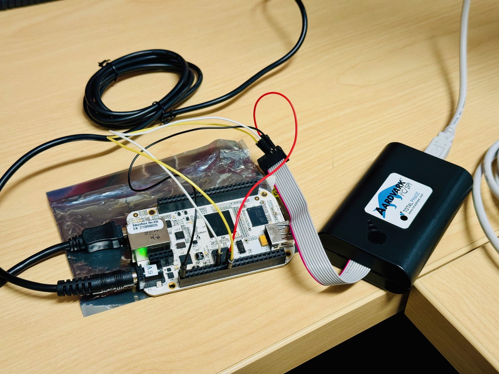
    I was able to set this up and the AM335x SPI slave transfer w/ external SPI master worked right away. Let me summarize everything so you can have this as a known good data point.

    From a HW POV, I used an AM335x-based BeagleBone board (SPI slave) and an external SPI host adapter (https://www.totalphase.com/products/aardvark-i2cspi/). The setup looks as follows:

    From a SW POV, I used the TI Linux Kernel, tag 09.02.00.010, as a base. Then, on top of this I applied the below diff, which is basically what you posted earlier. Here's again the actual diff for reference.

    a0797059@dasso:~/git/linux (ti-linux-6.1.y)
    $ git  diff
    diff --git a/arch/arm/boot/dts/am335x-bone.dts b/arch/arm/boot/dts/am335x-bone.dts
    index b5d85ef51a021..76862fcfd08df 100644
    --- a/arch/arm/boot/dts/am335x-bone.dts
    +++ b/arch/arm/boot/dts/am335x-bone.dts
    @@ -21,3 +21,29 @@ &ldo3_reg {
     &mmc1 {
            vmmc-supply = <&ldo3_reg>;
     };
    +
    +&am33xx_pinmux {
    +    spi0_pins: pinmux_spi0_pins {
    +        pinctrl-single,pins = <
    +                       AM33XX_IOPAD(0x950, PIN_INPUT | SLEWCTRL_FAST | MUX_MODE0) /* (A18) spi0_sclk.spi0_sclk */
    +                       AM33XX_IOPAD(0x954, PIN_OUTPUT | MUX_MODE0) /* (B18) spi0_d0.spi0_d0 MISO*/
    +                       AM33XX_IOPAD(0x958, PIN_INPUT | SLEWCTRL_FAST | MUX_MODE0) /* (B17) spi0_d1.spi0_d1 MOSI*/
    +                       AM33XX_IOPAD(0x95c, PIN_INPUT | SLEWCTRL_FAST | MUX_MODE0) /* (A17) spi0_cs0.spi0_cs0 */
    +       >;
    +    };
    +};
    +
    +&spi0 {
    +       status = "okay";
    +       pinctrl-names = "default";
    +       pinctrl-0 = <&spi0_pins>;
    +       ti,pindir-d0-out-d1-in = <1>;
    +       spi-slave;
    +       #address-cells = <0>;
    +
    +       slave@0 {       /* Define a SPI device at chip select 0 */
    +               compatible = "rohm,dh2228fv";
    +               spi-max-frequency = <16000000>; /* Set max SPI clock speed to 16MHz */
    +               spi-cpha;       /* SPI Mode 1 (CPOL=0, CPHA=1) */
    +       };
    +};
    

    Then, after setting up the Kernel defconfig as per SDK documentation, I also enabled the CONFIG_SPI_SLAVE=y option through `make ... menuconfig`, which is off by default.

    I then plugged the kernel, the Kernel modules, and the DTB file into (on top of) an SD card programmed with the tisdk-base-image from the AM335x SDK v9.1 installer, and booted the system. I also build and installed the `spidev` tool from the same Kernel tree.

    Then, I was able to run the command several times, each time followed up by running the host tool on the PC.

    Here are the logs from the AM335x platform...

    root@am335x-evm:~# ./spidev_test -D /dev/spidev0.0 -v -H
    spi mode: 0x1
    bits per word: 8
    max speed: 500000 Hz (500 kHz)
    TX | FF FF FF FF FF FF 40 00 00 00 00 95 FF FF FF FF FF FF FF FF FF FF FF FF FF FF FF FF FF FF F0 0D  |......@.........................|
    RX | 00 01 02 03 04 05 06 07 08 09 10 11 12 13 14 15 16 17 18 19 20 21 22 23 24 25 26 27 28 29 30 31  |.................... !"#$%&'()01|
    root@am335x-evm:~# ./spidev_test -D /dev/spidev0.0 -v -H
    spi mode: 0x1
    bits per word: 8
    max speed: 500000 Hz (500 kHz)
    TX | FF FF FF FF FF FF 40 00 00 00 00 95 FF FF FF FF FF FF FF FF FF FF FF FF FF FF FF FF FF FF F0 0D  |......@.........................|
    RX | 00 01 02 03 04 05 06 07 08 09 10 11 12 13 14 15 16 17 18 19 20 21 22 23 24 25 26 27 28 29 30 31  |.................... !"#$%&'()01|
    root@am335x-evm:~# ./spidev_test -D /dev/spidev0.0 -v -H
    spi mode: 0x1
    bits per word: 8
    max speed: 500000 Hz (500 kHz)
    TX | FF FF FF FF FF FF 40 00 00 00 00 95 FF FF FF FF FF FF FF FF FF FF FF FF FF FF FF FF FF FF F0 0D  |......@.........................|
    RX | 00 01 02 03 04 05 06 07 08 09 10 11 12 13 14 15 16 17 18 19 20 21 22 23 24 25 26 27 28 29 30 31  |.................... !"#$%&'()01|
    root@am335x-evm:~#
    

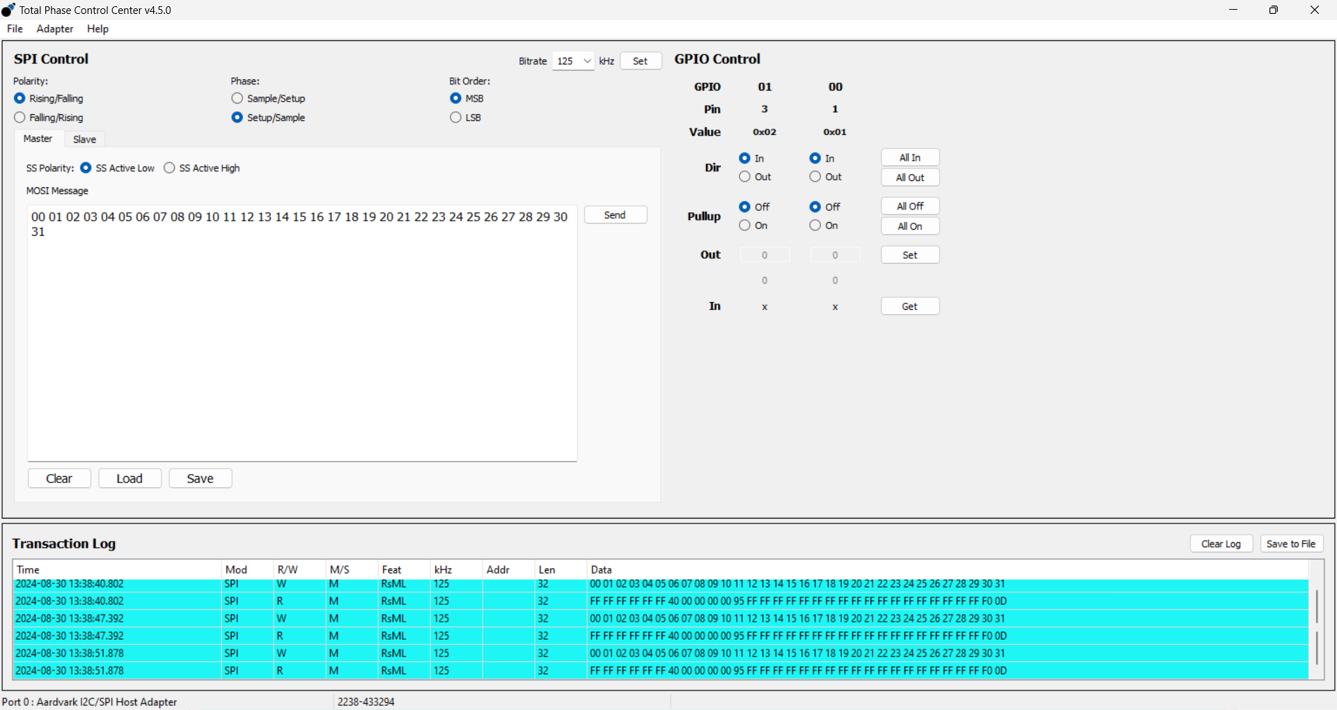
    ...and here's a screenshot from the host tool. Note how I was sending a sequence of 32 bytes (00 ... 31) which is correctly received on the AM335x. And in turn, the default data the `spidev` tool sends is received back on the host SPI master correctly (see the "Transaction Log" at the bottom of the screen).

    There was no issue or problem whatsoever. The only thing that I "learned" during this was that the `spidev` command line parameters for the SPI clock phase/polarity had to match what was setup in the device tree, as well as what's configured on the host side. For educational purposes I'll look into the source why those seemingly 2 redundant options exist on the target platform (DTS vs. command line parameter).

    Regards, Andreas

  • Hi Glen,

    But if the byte framing became misaligned, we would experience bursts of errors because it's not a dropped byte problem… EVERY byte is wrong until some time gap or restart.

    Correct.

    Let me know if you make any progress or can reproduce the failure (hang) of spidev_test on the Slave channel.

    See post above, I did not see any problem testing SPI slave operation.

    I'm not really sure the expected behavior of DMA RX on the slave channel when there is no master driving the clock (my current testbed w/o the Cheetah). I would expect it to perform the read on the spi device, a DMA Rx initiated and return zeros or garbage data, but not hang the system. 

    A SPI slave only works if it is clocked by the external master. If there is no clock, it will be forever waiting for incoming data. Unless a SW-based timeout mechanism is used. Why would you expect to return 0s without a clock being supplied?

    Regards, Andreas

  • Hi Andreas,
    That's promising a far as the spi-slave driver is concerned. Thank you.

    Now I have to figure out why our board worked fine with the custom slave driver and doesn't with the OMAP2-MCSPI spi-slave. The kernel logs during boot looks normal for both spi0 (slave) and spi1 (master). 

    I understand your other comments about why spidev_test is forever waiting for incoming data when there is no master to control the clock. On our board, the spi0 CS is always held low (at the moment) and the clk0 is driven by the other processor. I can see data on the spi0 MOSI when sent by the other processor. I currently don't understand why this is not seen through the DMA mechanism by the application on the AM3351 when it reads from /dev/spidev0.0. The Slave side application performs a poll/select() on /dev/spidev0.0 at a rate faster than the Master transmits. So, if there is data to be read the Slave should move it to the circular buffer before the Master can tx/overwrite it. The Slave never transmits anything to the Master over this device. Does the Slave need to see a CS transition from high to low, or is holding it low ok?

    I'll provide updates as applicable.

    Regards, Glen

  • I'll provide updates as applicable.

    Thanks Glen.

    Does the Slave need to see a CS transition from high to low, or is holding it low ok?

    It seems like while the HW McSPI peripheral supports host-slave CS signaling ("3 wire mode vs 4 wire mode"), and it really is needed to make certain scenarios work (CPOL=CPHA=0, Mode 0) so that the first bit gets output correctly, the Linux driver doesn't seem to use/configure this (remember how we had to remove the reg = <0> node that is usually required to select a CS signal, as this is a check enforced during DTS compilation). Looking at the McSPI HW registers (via `devmem2` for example) would allow to quickly confirm which mode the slave is in if you want to have a look (I don't have access to my HW right now).

    Note that I'm out of the office now, returning on 09/11, so will need pick things back up as needed after that. At a minimum you should be able to confirm/re-create working slave communication like I did.

    Regards, Andreas