This thread has been locked.

If you have a related question, please click the "Ask a related question" button in the top right corner. The newly created question will be automatically linked to this question.

DRA76P: USB Eye diagram failure

Part Number: DRA76P
Other Parts Discussed in Thread: DRA742

Tool/software:

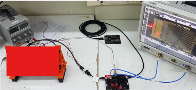
Hi, I'm using the DRA767P processor in an application featuring USB2.0 interface.

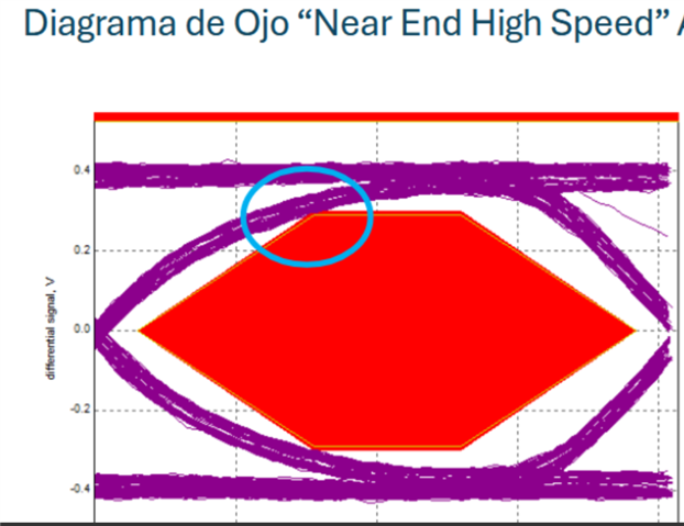
We run a preliminary test previous to USB-IF certification and we noted a slight deviation on the Eye diagram mask.

I wanted to know if there is any way to adjust physical parameters for USB PHY so we can pass this eye diagram test.

Thanks and regards, 

Augusto.

  • Hi Augusto,

    Can you describe (show pictures of?) your test setup (including equipment, cables, connectors)?

    Also provide a summary/image of your violation?

    Thanks,

    Kyle

  • Hi Kyle, 

    The setup used is based on TestUsb boards to enter the usb_packet mode and to connect the oscilloscope. I shaded the product due to confidentiality restrictions.

    The result can be depicted below. as you can see, we are marginally failing. 

    Please let me know your comments.

    regards, 

    Augusto.

  • Augusto,

    I see that the SMA cable connected to the scope is almost 18in; is there a shorter 6in cable that can be used instead, as it provides smaller insertion loss, resulting in a faster rising edge?

    https://e2e.ti.com/support/processors-group/processors---internal/f/processors---internal-forum/1324757/faq-dra7x-tda2x-omap5x-am57x-increasing-tx-amplitude-margin-for-usb2-0-by-tuning-the-termination-resistance

    This FAQ should apply to the DRA7xP too, and you could refer to this in case you need to increase the TX amplitude further to have a slightly higher margin on the near-end mask. Please let me know.

  • Hi Kyle,  thanks for your answer. The SMA cables used to run the measurement are part of the TESTUSB kit. I assume they are considered to be representative of what is going to be used in the final certification. I'm concerned about changing the cable, getting a pass and then being rejected by the laboratory. 

    regarding the link, I tried to access the app note but it says the link is not valid: 

    can you check it and sen again please?

    best regards

    Augusto.

  • Augusto,

    Here is the snippet of the USB drive eye mask improvement..

    "The fundamental idea would be to reduce termination resistance by a few counts to improve the eye diagram height. We would recommend tuning termination resistance first and then if that doesn‘t work it is recommended to optimize the channel USB cable.

    Address of registers

    Register

    Address in DRA742

    TERMINATION_CONTROL

    0x4a084000 (J6 USB2PHY2 - 0x4a085000)


    The register descriptions are below this text


    Adjusting termination resistance

    • Write 0 to TERMINATION_CONTROL.MEM_FS_CODE_SEL bits 27:24 in this register. This offset may be otherwise internally applied when the test pkt is being emitted. Make sure to do this step first because the value read in 5:0 will change once 0 is written to 27:24.
    • Read TERMINATION_CONTROL.RTERM_RMX (offset 0x00) bit 5:0.
    • Increase this value by 8-9 codes from the read value. 10 codes will provide ~2ohm decrease in output impedance. If untrimmed, you can use 21 as default. Depending on the exact system, you may have to go higher.

    Set TERMINATION_CONTROL.MEM_USE_RTERM_RMX_REG bit 21 as 1 and set the value from step 2 to MEM_RTERM_RMX (bit 20:15).


    TERMINATION_CONTROL

    Address Offset

    0x00

    Description

    contains bits related to control of terminations in USB2PHY

    Type

    RW


    31

    30

    29

    28

    27

    26

    25

    24

    23

    22

    21

    20

    19

    18

    17

    16

    15

    14

    13

    12

    11

    10

    9

    8

    7

    6

    5

    4

    3

    2

    1

    0


    Reserved

    mem_ALWAYS_UPDATE

    Reserved

    mem_FS_CODE_SEL

    Reserved

    mem_USE_RTERM_RMX_REG

    mem_RTERM_RMX

    Reserved

    mem_HS_CODE_SEL

    Reserved

    Reserved

    mem_DISABLE_TEMP_TRACK

    Reserved

    RTERM_RMX


    Bits

    Field Name

    Description

    Type

    Reset

    31:30

    Reserved


    RW

    0x0

    29

    MEM_ALWAYS_UPDATE

    When set to ‘1’, the calibration code is updated immediately after a code computation without waiting for idle periods.

    RW

    0

    28

    Reserved


    RO
    Rreturns0s

    0

    27:24

    MEM_FS_CODE_SEL

    FS Code selection control

    RW

    0x7

    23:22

    Reserved


    RW

    0x0

    21

    MEM_USE_RTERM_RMX_REG

    Override termination resistor trim code with mem_RTERM_RMX from this register

    RW

    0

    20:15

    MEM_RTERM_RMX

    The value written to this field is used as Termination resistor trim code  if bit 21 is set to ‘1’. Bits 5:2 of this are also used as rpu trim code if bit 21 is set.

    RW

    0x00

    14

    Reserved


    RO
    Rreturns0s

    0

    13:11

    MEM_HS_CODE_SEL

    HS Code selection control

    RW

    0x0

    10

    Reserved


    RO
    Rreturns0s

    0

    9

    Reserved


    RO
    Rreturns0s

    0

    8

    MEM_DISABLE_TEMP_TRACK

    Disables the temperature tracking function of the termination calibration

    RW

    0

    7:6

    Reserved


    RO
    Rreturns0s

    0x0

    5:0

    RTERM_RMX

    Returns the current value of RTERM_RMX

    RO
    Rreturns0s

    0x00