This thread has been locked.

If you have a related question, please click the "Ask a related question" button in the top right corner. The newly created question will be automatically linked to this question.

[FAQ] AM6548: AM6548 not booting from eMMC

Part Number: AM6548
Other Parts Discussed in Thread: TMDX654IDKEVM, UNIFLASH, DRA80XMEVM

Hello,

we experience problems booting an AM6548 from an eMMC in our custom board. Exactly the same binary, that is booting on the evaluation board (TMDX654IDKEVM) is not working on our custom board.

  • The bootmode pins are the same on both boards. --> Boot configuration is ok.
  • The custom board has a 25 MHz quarz. à Same as evaluation board and matches mcu bootmode configuration.
  • Uniflash is working fine when I boot the custom board in UART bootmode. --> The AM6548 on the custom board is working fine.
  • We can read and write the eMMC on the custom board in firmware when we start a firmware through JTAG. This way I validated that the firmware in the eMMC of the evaluation board and the custom board is the same. --> eMMC is working fine.
  • The ECSD registers of the eMMC on the custom board are set exactly the same as that ones of the evaluation board. --> eMMC is configured correctly.
    • We use partition BOOT0.
    • eMMC is configured for 8 bit data width in bootmode.
  • The eMMC is connected to MMC0 in exactly the same way on the custom board and the evaluation board. --> Bootmode pin configuration matches the hardware.

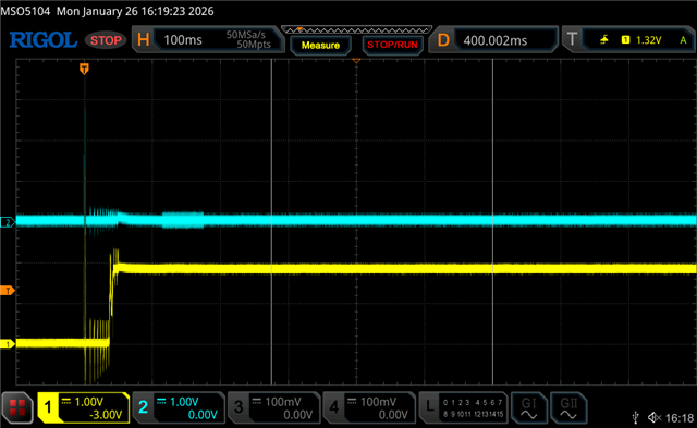
I notice that when I power up the evaluation board, I see the MMC0_CMD going low for a certain amount of time directly after it went high for the first time. I think this is to switch the eMMC to boot mode. On my custom board I don´t see this. It seems that the AM6548 is not trying to start from eMMC.

BOOTMODE0: High
BOOTMODE1: Low
BOOTMODE2: High
BOOTMODE3: High
BOOTMODE4: Low
BOOTMODE5: Low
BOOTMODE6: Low
BOOTMODE7: Low
BOOTMODE8: Low
BOOTMODE9: Low
BOOTMODE10: Low
BOOTMODE11: Low
BOOTMODE12: Low
BOOTMODE13: Low
BOOTMODE14: Low
BOOTMODE15: Low
BOOTMODE16: Low
BOOTMODE17: High
BOOTMODE18: Low

MCU_BOOTMODE0: High
MCU_BOOTMODE1: High
MCU_BOOTMODE2: Low
MCU_BOOTMODE3: Low
MCU_BOOTMODE4: Low
MCU_BOOTMODE5: Low
MCU_BOOTMODE6: High
MCU_BOOTMODE7: High
MCU_BOOTMODE8: Low
MCU_BOOTMODE9:  Low

Does anyone have an idea?

  • Hi Simon,

    Can you please re-test with a oscilloscope all BOOTMODE pins are at expected values around the time POR is being de-asserted after a power cycle?

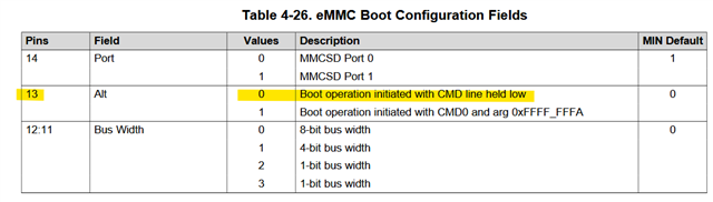
    It might be an external device driving one or more BOOTMODE pins leading to wrong boot mode being selected or e.g. pin 13 is selecting CMD0 with 0xFFFF_FFFA:

    Thanks,

    Stan

  • Hello Stan,

    I did the following test:
    1. Modified the SBL so it prints out the first parameter table on UART.
    2. Flashed this SBL into the evaluation board.
    3. Started the evaluation board with eMMC as primary boot mode and no backup boot mode.
    4. Saved the parameter table.
    5. Set the primary boot mode of the custom board to eMMC and the backup boot mode to ethernet.
    6. The custom board boots by ethernet one minute after I applied power.
    7. Saved the parameter table.

    After that I compared both parameter tables. Both are exactly the same, thus the boot mode pins are read correctly.

    Primary parameter table as Hexdump (startaddress: 0x41C7FC00, size: 512 Byte):

    1401000065000000102700001109ad011001000f00001900000040061900000000000000090019010400000009090e051100000f000019000000a00f3100000400000000090a3900190000000431091800000000000000000000000000000000000000000000000000000000000000000000000000000000000000000000000000000000000000000000000000000000000000000000000000000000000000000000000000000000000000000000000000000000000000000000000000000000000000000000000000000000000000000000000000000000000000000000000000000000000000000000000000000000000000000000000000000000000000000001010108001800a8610000400d0300803801000000000000000000000000000000000000000000000000000000000000000000000000000000000000000000000000000000000000000000000000000000000000000000000000000000000000000000000000000000000000000000000000000000000000000000000000000000000000000000000000000000000000000000000000000000000000000000000000000000000000000000000000000000000000000000000000000000000000000000000000000000000000000000000000000000000000000000000000000000000000000000000000000000000000000000000000000000000000000000

    Behavior of the evaluation board after power-up: Blue: MMC0_CLK, Yellow: MMC0_CMD

    Behavior of the custom board after power-up: Blue: MMC0_CLK, Yellow: MMC0_CMD

  • Hello Simon,

    What is the memory's part number on your board? 

    Thanks,

    Stan

  • Hello Stan,

    the eMMC is a SDINBDG4-8G-ZA2.

    Best regards

    Simon

  • Hello Simon,

    Thanks for the update !

    Stan is out of office today. He will be able to respond tomorrow.

    Thanks

    Best Regards,

    Anastas Yordanov

  • Hello,

    is there any update available on this?

    Kind regards

    Simon Tapmeyer

  • Hi Simon,

    I see the MMC0_CLK is NOT available on your custom board for some reason. Can you please check if the corresponding SoC pin output buffer is not forced to an OFF state in software (i.e. corresponding pad-configuration register bit[21] TX_DIS = 0b1) ? The TX_DIS bit should be set LOW to allow the MMC0 IP to output the clock signal at the SoC MMC0_CLK pin.

    Also, have you considered the following details from the AM6548 Datasheet below section regarding the SoC pin multiplexing settings of the MMCSD0 (eMMC) interface:

    Is the MMCSD0/1_SS_PHY_CTRL_1_REG[31] IOMUX_ENABLE set to 0b0 ?

    Please let us know !

    Thanks

    Best Regards

    Anastas Yordanov

  • Hi Anastas,

    I think there is a misunderstanding: The eMMC is working fine when we load and run our software through JTAG. The problem is that the AM6548 show no activity on the eMMC-Lines when we set the Boot-Pins to mode eMMC. In this case the ROM boot code is responsible for configuring the eMMC-Registers, padmux and so on.

  • Hi Simon,

    Thanks for the notes !

    I would like to apologize for incidentally omitting the JTAG test status you mentioned when thread was created.

    I can see from the schematic (SPRCAH0A_TMDX654IDKEVM DRA80XMEVM Design package\E4\PROC062E4(001)_SCH.pdf) the eMMC Flash MTFC16GAPALBH used on the TMDX654IDKEVM. Some eMMC Flash memories have internal volatile register bits that shall be additionally manipulated by the ROM loader to enable operation. Therefore, we need to internally check on the compatibility between the AM6548 ROM eMMC Boot code and your eMMC SDINBDG4-8G-ZA2 memory. Please expect our reply in one or two days.

    Thanks 

    Best Regards

    Anastas Yordanov

  • Hi Anastas,

    we made sure that the boot process related configuration of the ECSD registers in the eMMC on our custom board is exactly the same as on the evaluation board.

    The problem we see is that the AM6548 isn´t even putting a clock on the CLK line to the eMMC. We should see this clock signal even if the AM6548 ROM and the eMMC would not be compatible.

    We made sure that the eMMC is powered before the AM6548. Could there be a problem in the power up sequencing of the AM6548 that would lead to this behavior? Please consider that we can successfully boot the AM6548 by ethernet or uart boot mode. Only the eMMC boot mode is not working.

  • Hi All,

    The below FAQ includes the notes for the power sequence diagrams.

    (+) [FAQ] AM654x, AM652x : Data sheet Documentation (about timing) of the power sequencing - Processors forum - Processors - TI E2E support forums

    Simin, can you please confirm if you have shared the schematics with TI team to do a quick check.

    Regards,

    Sreenivasa

  • Hi Screenivasa,

    we can´t share the schematic here in this thread but we could do directly with you if you provide me an email address.

    Kindly regards

    Simon Tapmeyer

  • Hello Simon Tapmeyer

    Thank you and noted.

    Please use the private chat to share.

    Please ping me and based on the connection acknowledgement - you can share the schematics. 

    Regards,

    Sreenivasa

  • Hello,

    finally and with the help of  from TI our hardware engineer was able to fix the problem. The MMC0_SDCD is connected through a 22k resistor to GND. This was too much. The eMMC boot mode is working fine since we replaced the 22k resistor by a 10k resistor. The evaluation board uses a 10k resistor as well. Thanks to TI for the support.

    Best regards

    Simon Tameyer

  • Hello Simon Tapmeyer

    Thank you for adding your test observations.

    Regards,

    Sreenivasa 

  • Hello Simon Tapmeyer

    Thank you for the discussions regarding the pulldown value.

    As mentioned in the discussion, the 22K on the customer board as well as the 10K on the EVM can be reduced to a lower value (100R or 1K).

    Regards,

    Sreenivasa

  • Hello Simon,

    Refer below inputs i received from the design team:

    In AM65x devices, the MMC0_SDCD pin was unexpectedly configured with DEVICE_PINMUX_PULL_ENABLE and DEVICE_PINMUX_PULL_UP, causing an internal pull-up resistor to conflict with external pull-down resistors and preventing proper eMMC boot operation.

    As i mentioned please use a strong pull (100R - 1K) as pulldown

    The pulldown value is to ensure there is a current limit in case the IO is configured as output unexpectedly.

    Regards,

    Sreenivasa