This thread has been locked.

If you have a related question, please click the "Ask a related question" button in the top right corner. The newly created question will be automatically linked to this question.

EDMA Slow Transfer speed

Hi,

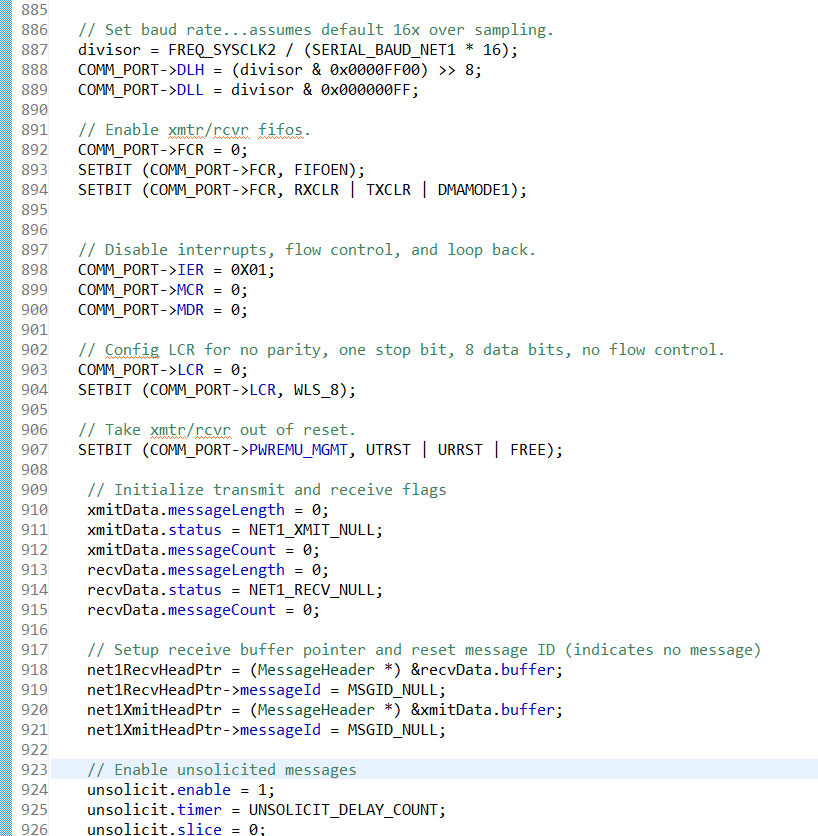
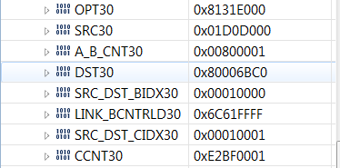
I'm currently using the EDMA3 on the C6748 to transfer incoming variable length UART data to memory one byte at a time. At the end of each transfer (data stops coming in) the registers are reloaded in code. The transfers are occurring properly, the problem is there is only a single transfer every 300us or so. The internal clock is approximately 300MHz. I have attached the register set up for the transfer. Any insight to the situation, or how to speed up the transfer would be appreciated. If anymore information is needed ask and I'll get it to you asap.


Thank you

Sam

  • Sam,

    Welcome to the TI E2E forum. I hope you will find many good answers here and in the TI.com documents and in the TI Wiki Pages. Be sure to search those for helpful information and to browse for the questions others may have asked on similar topics.

    Why do you suspect EDMA3 for this issue? Have you run this using a DSP polling loop and measured the time between transfers with different results?

    What is your baud rate on the UART serial line? A 300us byte rate matches well to 11 bits at 36K baud.

    What does the Rx pin look like on a scope? Some of the other handshaking lines might also be working, RTS/CTS.

    Regards,
    RandyP

  • Rand,

    Thanks for the reply,

    • Why do you suspect EDMA3 for this issue? Have you run this using a DSP polling loop and measured the time between transfers with different results?

    We poll the DMA once ever 500us to see if any transfers have occurred and we operate a state machine off of it. I set up an array to log how many transfers have occured every time we poll, it is consistently 1-2 transfers new every time through. (amount of transfers is determined via the current BCCNT vs the originally set BCCNT). 

    • What is your baud rate on the UART serial line? A 300us byte rate matches well to 11 bits at 36K baud.

    115.2K Baud and 9 bits

    •  What does the Rx pin look like on a scope? Some of the other handshaking lines might also be working, RTS/CTS.

    The Rx pin looks normal on the scope. The individual bits were not investigated but the timing was correct for the size of the message at 9 bits and 115,200 Baud. We ran a test where we toggled another Pin every time the DMA is polled. The Rx pin looks normal coming in, less than 500uS later the first poll occurs. After about 5 more times through the loop the message is fully received. 

    All of these things point me towards issues with the DMA, I just don't know what.

    Thank you for your time,

    Sam

  • Sam,

    Sam Swerdlow said:
    115.2K Baud and 9 bits

    9 might be a setup value but it is not a hardware value. A UART will always have at least 1 start bit, 8 data bits, and 1 stop bit. If you have added parity or a second stop bit, that will increase it past the minimum 10.

    Can you paste or attach a logic analyzer or scope picture showing multiple data bytes on the Rx line and your "other pin" that shows the 500us polling period? For me to help you debug this remotely, which I will do, I need more than "looks normal" to close the loop and find a cause/solution.

    To understand the UART peripheral's operation, it will help to setup a DSP polling loop only for reading the UART (not the DMA) and do not use the DMA. We can see how often you get data in that case to get a solid line to start from.

    Be patient and precise with me and we can do this. I know remote is tough to keep the remote side informed, but I will be counting on you to do that.

    Regards,
    RandyP

  • We are running 10 HW bits (I forgot to add the start bit). Also the loop time was set to 1ms during these pictures, the error still exists.

    I have a few pictures for you. 

    The first shows the Rx pin in purple, and the polling in green. We set the line low when we first get around to it, and set it high when we come around and see we have the whole message.

    The second picture is the same thing but with the DMA.

    The third is just the Rx bits zoomed in.

    I hope these are helpful.

    Thank you for your time

    Sam

  • Sam,

    Thanks for the pictures, which of course lead to clarifying questions:

    In the first picture (No DMA?):

    N1. Are you polling the UART's registers or waiting for a UART Ready interrupt?
    N2. Do you get all 10 bytes of data correctly by the time the green pin goes high?
    N3. Are you using the UART in FIFO mode (what is the threshold value) or non-FIFO mode?

    In the second picture (DMA):

    D1. Are you using the UART in FIFO mode (what is the threshold value) or non-FIFO mode?
    D2. Do you get all 10 bytes of data correctly by the time the green pin goes high?
    D3. Can you share some code that shows what you are doing in terms of polling and responding to that?

    Regards,
    RandyP

  • Randy,

    Of course it does, there are always more questions!

    N1. This is the same polling loop as before.

    N2. All 10 bytes are correctly received when the green pin goes high. The code requires at least two times through in order to tell if it has all of the data, so the 10 bytes may be correctly received well before the line goes high.

    N3. We are in FIFO Mode,1 byte will raise the receive data interrupt (nothing other than DMA mode was set in the FCR) Is that what you meant by threshold?

    D1. Yes the UART is still in FIFO mode with a threshold of 1.

    D2. All of the 10 data bytes are correctly read in when the green pin goes high.

    D3. I've attached the code for polling and setting the LED pin. I also included the DMA set up, figuring you may very well need it down the road.

    This code is the statemachine for incoming data
    
    
    #ifndef DISABLE_DMA_NET1  //if the DMA is active
        //COMM_PORT->FCR |= RXCLR;
        //if we previously received an entire message, do nothing until the message has been processed.
    
        if (recvData.status == NET1_RECV_MESSAGE)
        {
        }
    
        // Otherwise if we are receiving characters, check for any new ones
        else if (recvData.status == NET1_RECV_ACTIVE)
        {
        	// If there is a flag clear it
            if (((0x01 << DMA_INPUT_CHANNEL) & (edma_getIntrStatus(DMA_CONTROLLER_ADDRESS))) != 0)
        	{
            	// TCODE
    //            if (++kme & 1)
    //        	    DOUT_SET_LED_BLU    // TCODE GOES HI
    //            else
    //            	DOUT_CLR_LED_BLU    // TCODE GOES LO
    
            	edma_clrIntr (DMA_CONTROLLER_ADDRESS, DMA_INPUT_CHANNEL);
    
                //TCODE
                sjsvect[sjsi]=edma_getAccntLength (DMA_INPUT_CHANNEL, DMA_CONTROLLER_ADDRESS);
                sjsi++;
    
        	}
        	// Else transfer complete, calc Length, update global flag, update state machine, renew params
        	else
        	{
        		//tcode
        		sjsi=0;
        	    DOUT_SET_LED_BLU    // TCODE GOES HI
        		recvData.status = NET1_RECV_MESSAGE;
        		recvData.messageLength = edma_getAccntLength (DMA_INPUT_CHANNEL, DMA_CONTROLLER_ADDRESS);
        		edma_channelToParamMap (DMA_CONTROLLER_ADDRESS, DMA_INPUT_CHANNEL, DMA_INPUT_RELOAD_CHANNEL); //should probably be done when the signal is being figured out
        	}
        }
        // Otherwise if we received any characters, then a new message has started
        else if (((0x01 << DMA_INPUT_CHANNEL) & (edma_getIntrStatus(DMA_CONTROLLER_ADDRESS))) != 0)
        {
    	    DOUT_CLR_LED_BLU    // TCODE GOES LO
            recvData.status = NET1_RECV_ACTIVE;			// Update state machine, clear flag
            edma_clrIntr (DMA_CONTROLLER_ADDRESS, DMA_INPUT_CHANNEL);
            //COMM_PORT->FCR |= RXCLR;
        }
    
    
    /////////////////////////////////////////////////////////////////
    This code is how we initialize the DMA
    /////////////////////////////////////////////////////////////////
    void net1_edmaInitialize (void)
    {
        int i;
    
        // DATA PARAMETERS PROVIDED BY APPLICATION
        // Configure EDMA for UART Inputs
        unsigned int chType     = EDMA3_CHANNEL_TYPE_DMA;
        unsigned int chNum      = DMA_INPUT_CHANNEL;
        unsigned int reloadParamChNum = DMA_INPUT_RELOAD_CHANNEL;  // Set this up now, it is to be used by the Reading Function
        unsigned int tccNum     = DMA_TRANSFER_CONTROLLER;
        unsigned int evtQ       = EVENTQ;    // Event Queue used
    
        EDMA3Init(DMA_CONTROLLER_ADDRESS, evtQ);
    	volatile char *srcBuff;
    	volatile char *dstBuff;
        volatile unsigned int count = 0;
        unsigned int retVal = 0u;       // retVal is only needed to allow IT code to remain unchanged
    
        unsigned int acnt = MAX_ACOUNT;
        unsigned int bcnt = MAX_BCOUNT;
        unsigned int ccnt = MAX_CCOUNT;
    
        srcBuff = (char *) COMM_BASE;
        dstBuff = (char *) recvData.buffer;
        for (i = 0; i < 127; i++)
        	recvData.buffer[i] = 0XFF;
    
        retVal = edma_requestChannel(DMA_CONTROLLER_ADDRESS, chType, chNum, tccNum, evtQ);
        retVal = edma_requestChannel(DMA_CONTROLLER_ADDRESS, chType, reloadParamChNum, tccNum, evtQ);
    
        // Fill the PaRAM Set with transfer specific information
        paramSet.srcAddr  = (unsigned int) (srcBuff);
        paramSet.destAddr = (unsigned int) (dstBuff);
    
        paramSet.aCnt = (unsigned short) acnt;
        paramSet.bCnt = (unsigned short) bcnt;
        paramSet.cCnt = (unsigned short) ccnt;
        paramSet.linkAddr = 0xFFFF;
        // Setting up the SRC/DES Index
        paramSet.srcBIdx = 0;    //Static Uart Source
        paramSet.destBIdx = (short) acnt;
    
        // A Sync Transfer Mode
        paramSet.srcCIdx = (short) acnt;
        paramSet.destCIdx = (short) acnt;
    
        //  Enable Final transfer completion interrupt flag, and dynamic destination addressing
        paramSet.opt = 0;
        paramSet.opt |= (chNum << EDMA3CC_OPT_TCC_SHIFT);
        paramSet.opt |= (1 << EDMA3CC_OPT_TCINTEN_SHIFT);
        paramSet.opt |= (1 << EDMA3CC_OPT_ITCINTEN_SHIFT);
        paramSet.opt &= 0xFFFFFFFB;
    
        // Now, write the PaRAM Sets.
        edma_clrIntr (DMA_CONTROLLER_ADDRESS, chNum);
        edma_setParam (DMA_CONTROLLER_ADDRESS, chNum, &paramSet);
        edma_setParam (DMA_CONTROLLER_ADDRESS, reloadParamChNum, &paramSet);
        edma_enableDmaEvt (DMA_CONTROLLER_ADDRESS, chNum);
    
        chNum      = DMA_OUTPUT_CHANNEL;  //initialize the output channel as well.
        retVal = edma_requestChannel(DMA_CONTROLLER_ADDRESS, chType, chNum, tccNum, evtQ);
    
        //assemble PaRAM information
        srcBuff = (char *) xmitData.buffer;
        dstBuff = (char *) COMM_BASE;
    
        // Fill the Param Set with transfer specific information except Bcnt
        paramSet.aCnt = (unsigned short) acnt;
        paramSet.cCnt = (unsigned short) ccnt;
        paramSet.linkAddr = 0xFFFF; //Turn off after message is complete
        // Setting up the SRC/DES Index
        paramSet.srcBIdx = (short) acnt;  //Static Uart Source
        paramSet.destBIdx = 0;
        paramSet.srcAddr  = (unsigned int) (srcBuff);
        paramSet.destAddr = (unsigned int) (dstBuff);
        // A Sync Transfer Mode
        paramSet.srcCIdx = (short) acnt;
        paramSet.destCIdx = (short) acnt;
    
        // Enable Final transfer completion interrupt flag, and dynamic destination addressing
        paramSet.opt = 0;
        paramSet.opt |= (1 << EDMA3CC_OPT_TCINTEN_SHIFT);
        paramSet.opt |= (EDMA3CC_OPT_DAM);
        paramSet.opt &= 0xFFFFFFFBu;    //A type transfer
    

    Best of luck

    Sam

  • Sam,

    Some quick comments between meetings, and I will try to get back while flying home tonight.

    N1. I am not sure what you are polling on, the interrupt flag being set or the ready bit in the UART.

    N2. If you poll the ready line and read some data, then you will wait for another polling loop to either check for ready again or note that the full 10 has been received. Is that correct? Is it true that there would always be some number of data-read passes through the loop and then one more pass to note the completion?

    N3. I will have to study the UART User Guide to understand the operation of the FIFO. When you get the data interrupt, you do not do anything until you make another pass through the polling loop, right?

    D1. I will have to study the UART User Guide to understand the operation of the FIFO and when it sends a DMA event.

    D2. The DMA will read 1 byte every time it gets an event from the UART to trigger it. If there is a long time between one read and the next (the 300us delay we are talking about), then something has to trigger the DMA UART Rx Channel to go read one more byte each time. I did not notice that being done in the polling loop, so I do not understand how the data gets read, unless the UART will repeatedly send events until it is empty. The EDMA3 should respond to each event very quickly.

    D3. Some code comments/questions:
    a. edma_getAccntLength - the name implies you are reading ACNT, but ACNT should always read 1 from the values in your first post. What is this doing?
    b. You are writing to a reload Param, but you set the linkAddr to 0xFFFF. Do you have other plans for the reload (link) Param? It is not going to be used in this case, with Link = 0xFFFF.
    c. srcCIdx should also be 0, like srcBIdx. It will not show up until you exhaust the BCNT field, which will only happen for a long message. This appears in two places.
    d. There are two sets of assignments to load paramSet. In the set after the "Now, write the PaRAM Sets" part, there is a line with an unknown (to me) value of EDMA3CC_OPT_DAM. You do not want to set the DAM or SAM bits to 1. This code may be for the Tx side, but you still do not want to set SAM or DAM.

    My best guess right now is that the problem has to do with the interaction between the UART FIFO and its signalling an event to the EDMA3 module and then sending another event to the EDMA3 module. But my current understanding of your flow does not give me any quick guesses about how this all could work or does work.

    Would it be possible to setup a test where you service the UART using a DSP interrupt routine, and let it read one byte each time the interrupt comes in, like the EDMA3 would do? In that ISR you could pulse your GPIO pin, or another one, to see how long it is after the RXD line before you get into the ISR and out of it.

    Another related test, both with the DSP ISR and with the DMA would be to send the message one byte at a time, with a long time between them, like 300us or more. That would help to narrow the search for the delay point.

    Next meeting starts now...

    Regards,
    RandyP

  • Randy,

    Thanks for the quick reply

    • N1. I am not sure what you are polling on, the interrupt flag being set or the ready bit in the UART

    We poll the ready bit in the UART

    • N2. If you poll the ready line and read some data, then you will wait for another polling loop to either check for ready again or note that the full 10 has been received. Is that correct? Is it true that there would always be some number of data-read passes through the loop and then one more pass to note the completion?

    Correct, and Correct. The minimum number of passes is two (all data would have to come in in between polls)

    • N3. I will have to study the UART User Guide to understand the operation of the FIFO. When you get the data interrupt, you do not do anything until you make another pass through the polling loop, right?

    Our communications are in a master/slave relationship. After we start receiving we do not do any more processing dealing with communications until we check again.

    • D1. I will have to study the UART User Guide to understand the operation of the FIFO and when it sends a DMA event.

    Sounds good

    • D2. The DMA will read 1 byte every time it gets an event from the UART to trigger it. If there is a long time between one read and the next (the 300us delay we are talking about), then something has to trigger the DMA UART Rx Channel to go read one more byte each time. I did not notice that being done in the polling loop, so I do not understand how the data gets read, unless the UART will repeatedly send events until it is empty. The EDMA3 should respond to each event very quickly.

    If i'm not mistaken (please check my initialization) I have the DMA UART Rx Channel to trigger off of the UART data ready flag. But yes, this is really the source of confusion.

    • a. edma_getAccntLength - the name implies you are reading ACNT, but ACNT should always read 1 from the values in your first post. What is this doing?

    perhaps edma_getAccntCount would be a better name. This function subtracts the current Bccnt from the original Bccnt. This gives the total number of transfers triggered. It was used for debugging purposes. 

    • b. You are writing to a reload Param, but you set the linkAddr to 0xFFFF. Do you have other plans for the reload (link) Param? It is not going to be used in this case, with Link = 0xFFFF.

    We link to 0xFFFF for debugging reasons, we reload with channel 28 after the data has been recieved and processed. We don't know the length of the messages coming in so we can't count on running through Accnt x Bccnt transfers to restart.

    • c. srcCIdx should also be 0, like srcBIdx. It will not show up until you exhaust the BCNT field, which will only happen for a long message. This appears in two places.

    Good to know what I messed up shouldn't impact the problem, I will change this.

    • d. There are two sets of assignments to load paramSet. In the set after the "Now, write the PaRAM Sets" part, there is a line with an unknown (to me) value of EDMA3CC_OPT_DAM. You do not want to set the DAM or SAM bits to 1. This code may be for the Tx side, but you still do not want to set SAM or DAM.

    That is for the Tx side, after reviewing the datasheet a bit closer I will remove these.

    I will go and make these minor changes, and get back to you when ever the test station gets open.

    Thank you for your help and time,

    Sam

  • Randy, 

    I will not be able to complete the tests today, but I do have some questions. Would it be good enough to just pulse the GPIO pin in the ISR? The system would still have to go through the state machine (and would, successfully). Do you want me to remove the state machine or replace it with something else? If so, what?

    And I can delay the bytes easily enough, but what would you like to see if I run with the ISR and DMA?

    Sam

  • Sam,

    I am trying to think this through and have been staring at your DMA state machine to try to understand it. When it takes such a long time to get the data using the DMA method, what are some example contents of your sjsvect array? I assume it is a sequence of numbers increasing from 1 to 10, with a new entry each time you go into the state machine until the message is noted to be complete. Could you move the sjsi=0; statement to the last state machine part where a new message starts, and include sjsi in the sjsvect displays, please?

    The purpose of using the ISR is to be able to mark the timing of the same signal (interrupt) as the DMA event that triggers the DMA channel to run. It might not be needed, but it could be helpful. Looking at the non-DMA polling code and seeing the sjsvect displays could help as much with understanding what is going on.

    Regards,
    RandyP

  • Randy,

    I have the ISR working, figured I'd give you a quick update before lunch. 

    • When it takes such a long time to get the data using the DMA method, what are some example contents of your sjsvect array?

    Your prediction is mostly accurate. I have never seen it start at one. But most samples tend to be along the lines of [2,3,5,6,8,9,10]. One or two transfers every 500us.

    • The purpose of using the ISR is to be able to mark the timing of the same signal (interrupt) as the DMA event that triggers the DMA channel to run. It might not be needed, but it could be helpful. Looking at the non-DMA polling code and seeing the sjsvect displays could help as much with understanding what is going on.

    No pictures yet ( I can get you on after lunch) but I have ran the system pulsing the LED on the Uart2 data available ISR. The ISR waits about 200-300 us before triggering, the same amount of time as the DMA takes to start transferring in the above pictures. 

    I plan on getting you a picture of a typical sjsvect, the ISR pulse while running in UART only mode, and the ISR pulse, and the State Machine "pulse" in DMA mode. Do you need anything else?

    Thanks,

    Sam

  • Sam,

    Is it correct that the ISR reads only 1 byte from the UART's receive FIFO and then returns from the ISR? And the DMA is not enabled in this case, right?

    The fact that the ISR waits 200-300 us between interrupt events means that the problem is not in the EDMA3's setup or in the ISR's setup, since they were done independently and get the same results.

    So there is something in the UART's operation that leads it to wait a long time to send out the next event. Maybe this is programmable - a delayed event trigger if there is more data in the FIFO.

    I mentioned a method (untested) to generalize the process of using the EDMA3 efficiently (reading more than 1 byte at a time) with a timer-based poll for whether a message has completed. That discussion was in my first reply on this thread.

    The best use of the EDMA3 is for reading data from the FIFO in chunks instead of just one-at-a-time. That conflicts with the need to have an unknown number of bytes in the message, and it conflicts with the efficiency of reading more than 1 byte when an event is sent to the DMA.

    If you let the UART send an event to the DMA only when there are at least 8 bytes to be read, then your DMA operation will be efficient. When your timer-based polling routine checks and sees that there has been data read by the DMA, it can check the FIFO to see if there is any data there. The next time the routine comes around, if there has been no more data read and no new data in the FIFO, you may be able to assume the message is complete.

    That was not a very involved explanation, but we can discuss it more if you are interested.

    Your solution may be changing how often the UART repeats pending events. But that could be combined with the DMA change to make it all work well together.

    Regards,
    RandyP

  • Randy,

    • Is it correct that the ISR reads only 1 byte from the UART's receive FIFO and then returns from the ISR? And the DMA is not enabled in this case, right?

    The actual movement of data is not done in the ISR, we only toggled the pin. The DMA is not enabled. here is a picture of the event. 

    Even though it seems superfluous I may as well upload the other tests ran. The following is the same test as above but with the FIFO disabled. The fact that it triggers earlier also supports the UART configuration error you proposed.

    The last is triggering the interrupt, and measuring the state machine timing in DMA mode.

    Would changing the DMA operation as you suggested (8 bytes at a time, also check the FIFO to verify no new data) make the DMA trigger any sooner? Regardless I plan on going and poking around the UART to see if I can get it to trigger sooner.

    Thank you for your help, I'll be back in a day or so if we can't find it. If I do find it I'll also be sure to come back and confirm my question answered.

    Sam

  • Randy,

    I ran a few more tests, while looking at the UART config a bit closer. I noticed that the delay from the end of incoming bytes as well as in between was 4 character lengths, suggesting that the timeout interrupt is triggering and not the FIFO data ready interrupt. This absolutely perplexes me as I think that we set that portion up correctly. I've attached our UART registers as well as the code for setting them up. Do you see anything that I don't?

    Thank you for your time and expertise on this matter,

    Sam Swerdlow

  • Sam,


    I think there are a couple of things going on here. The FCR configuration needs to be done differently and the DMA transfer needs to read more than 1 byte at a time. Here is what I am thinking:

    FCR configuration:

    Write-only registers are a big inconvenience. I have no idea why a chip designer would try to conserve register addresses in a 32-bit architecture, but someone decided to overlap the read-only IIR register with the write-only FCR. This means that when you do a read-modify-write operation like SETBIT(COMM_PORT->FCR, FIFOEN), it does not read the 0 previously written to FCR but instead reads whatever is in IIR, modifies that and writes out IIR+FIFOEN; not what you want to happen.

    There is a Caution in the TRM for the FCR saying

    TRM 30.3.5 CAUTION said:
    For proper communication between the UART and the EDMA controller, the
    DMAMODE1 bit must be set to 1. Always write a 1 to the DMAMODE1 bit, and
    after a hardware reset, change the DMAMODE1 bit from 0 to 1.

    My recommendation is to use the following 2 writes to make sure this Caution is met:

    COMM_PORT->FCR = 0;
    COMM_PORT->FCR = FIFOEN | DMAMODE1 | CHAR? | RXCLR | TXCLR;
    COMM_PORT->FCR = FIFOEN | DMAMODE1 | CHAR?;

    The extra writes are for an overabundance of caution and the last one may not be needed. The first one may not be needed either, but it might be an implied requirement from the Caution.

    The CHAR "?" is because I am not sure yet what you will want to choose for your FIFO Threshold. That is discussed later in this post.

    DMA operations:

    They had something great in mind when they put in the timeout event to tell the DMA to get some more data. What appears to be happening in your case is that the FIFO Threshold is set to 14 bytes and the DMA only reads 1 byte each time it gets an event. So this is what is happening:

    1. Byte1 comes in and reaches the FIFO. Since the TL is set to 14, no DMA event is generated, yet.
    2. Byte2 comes in and reaches the FIFO. Still no TL event and since the bytes are coming in continuously,, no timeout occurs.
    3. ByteN (the last of the message, maybe 10?) gets to the FIFO, not up to TL, so still no DMA event requested.
    4. 4 character times later, the timeout is asserted and the DMA event is triggered. The EDMA3 reads 1 byte.
    5. Another 4 character times after #4, another timeout causes 1 more byte to be read.
    6. Step 5 is repeated until all the bytes have been read from the FIFO.

    The total time required is about 5 times as long as the message took to come in - 1x for the actual data to be shifted in + 4 char-times per byte for the timeout. I think that approximately matches the delay you are seeing, since my first estimate was a 33KBaud rate and you said you were running at 115K, about 4x my guess.

    There are a couple of difficulties that I see with fixing this:

    a. You cannot distinguish between a FIFOTL DMA event (telling you to read 8 bytes if TL=8) and a timeout DMA event (telling you there is some unknown amount of data < TL in the FIFO).
    b. If you program the DMA to read TL bytes each time (the normal thing to do), then when the timeout occurs you will read another TL bytes even if there is only 1 byte left in the FIFO. I do not know what you get when you underrun the FIFO like that: duplicates of the last byte or 0's or stale data from the FIFO (like 16 bytes ago).
    c. It might be a very low probability, but I can picture a race condition when a timeout occurs with only 1 byte in the FIFO, the DMA goes to read 8 bytes (TL=8), and while those 8 bytes are being read another byte is received from the UART and put into the FIFO. Could the new byte be read as one of the "trash" bytes?

    If it is trivial for your system to know how long a message was supposed to be, and if there are always sufficient gaps between messages to allow the timeout to empty the FIFO, then setting TL=8 and ACNT=1/BCNT=8/CCNT=256/Sync=ABSYNC will get you good data with only a single 4 byte delay at the end of a message.

    You might be able to get rid of your own 300us timer to test for incoming data, but maybe not. One idea might be to set TL=14 and keep the 8-byte read in the DMA. Then you would always get a timeout at the end of a message, never hitting the exact multiple of 8. You could set the interrupt to the CPU to occur only in case of a timeout, and that would give you a clear signal that the DMA has read a full message in for you.

    That is probably enough for me to write right now. Let me know what you think about this much of it and we can continue the direction you want to go.

    Regards,
    RandyP

  • Randy,

    It works! I had thought that the buffer size was the problem before, but I checked our initialize and was convinced it should work. I changed out he SetBit function as you suggested and everything began working as intended. Thank you very much for your help.

    Sam