

Hi,
Use the I2C module to digital echo test. Programming as follows:
#include <csl.h>
#include <csl_i2c.h>
#include <stdio.h>
#include <csl_pll.h>
#include <csl_mcbsp.h>
#define CODEC_ADDR 0x1A
PLL_Config myConfig = {
0,
1,
12,
1
};
MCBSP_Config Mcbsptest;
/*McBSP set,we use mcbsp1 to send and recieve the data between DSP and AIC23*/
MCBSP_Config Mcbsp1Config = {
MCBSP_SPCR1_RMK(
MCBSP_SPCR1_DLB_OFF, /* DLB = 0,禁止自闭环方式 */
MCBSP_SPCR1_RJUST_LZF, /* RJUST = 2 */
MCBSP_SPCR1_CLKSTP_DISABLE, /* CLKSTP = 0 */
MCBSP_SPCR1_DXENA_ON, /* DXENA = 1 */
0, /* ABIS = 0 */
MCBSP_SPCR1_RINTM_RRDY, /* RINTM = 0 */
0, /* RSYNCER = 0 */
MCBSP_SPCR1_RRST_DISABLE /* RRST = 0 */
),
MCBSP_SPCR2_RMK(
MCBSP_SPCR2_FREE_NO, /* FREE = 0 */
MCBSP_SPCR2_SOFT_NO, /* SOFT = 0 */
MCBSP_SPCR2_FRST_FSG, /* FRST = 0 */
MCBSP_SPCR2_GRST_CLKG, /* GRST = 0 */
MCBSP_SPCR2_XINTM_XRDY, /* XINTM = 0 */
0, /* XSYNCER = N/A */
MCBSP_SPCR2_XRST_DISABLE /* XRST = 0 */
),
MCBSP_RCR1_RMK(
MCBSP_RCR1_RFRLEN1_OF(1), /* RFRLEN1 = 1 */
MCBSP_RCR1_RWDLEN1_16BIT /* RWDLEN1 = 2 */
),
MCBSP_RCR2_RMK(
MCBSP_RCR2_RPHASE_SINGLE, /* RPHASE = 0 */
MCBSP_RCR2_RFRLEN2_OF(0), /* RFRLEN2 = 0 */
MCBSP_RCR2_RWDLEN2_8BIT, /* RWDLEN2 = 0 */
MCBSP_RCR2_RCOMPAND_MSB, /* RCOMPAND = 0 */
MCBSP_RCR2_RFIG_YES, /* RFIG = 0 */
MCBSP_RCR2_RDATDLY_1BIT /* RDATDLY = 1 */
),
MCBSP_XCR1_RMK(
MCBSP_XCR1_XFRLEN1_OF(1), /* XFRLEN1 = 1 */
MCBSP_XCR1_XWDLEN1_16BIT /* XWDLEN1 = 2 */
),
MCBSP_XCR2_RMK(
MCBSP_XCR2_XPHASE_SINGLE, /* XPHASE = 0 */
MCBSP_XCR2_XFRLEN2_OF(0), /* XFRLEN2 = 0 */
MCBSP_XCR2_XWDLEN2_8BIT, /* XWDLEN2 = 0 */
MCBSP_XCR2_XCOMPAND_MSB, /* XCOMPAND = 0 */
MCBSP_XCR2_XFIG_YES, /* XFIG = 0 */
MCBSP_XCR2_XDATDLY_1BIT /* XDATDLY = 1 */
),
MCBSP_SRGR1_DEFAULT,
MCBSP_SRGR2_DEFAULT,
MCBSP_MCR1_DEFAULT,
MCBSP_MCR2_DEFAULT,
MCBSP_PCR_RMK(
MCBSP_PCR_IDLEEN_RESET, /* IDLEEN = 0 */
MCBSP_PCR_XIOEN_SP, /* XIOEN = 0 */
MCBSP_PCR_RIOEN_SP, /* RIOEN = 0 */
MCBSP_PCR_FSXM_EXTERNAL, /* FSXM = 0 */
MCBSP_PCR_FSRM_EXTERNAL, /* FSRM = 0 */
0, /* DXSTAT = N/A */
MCBSP_PCR_CLKXM_INPUT, /* CLKXM = 0 */
MCBSP_PCR_CLKRM_INPUT, /* CLKRM = 0 */
MCBSP_PCR_SCLKME_NO, /* SCLKME = 0 */
MCBSP_PCR_FSXP_ACTIVEHIGH, /* FSXP = 0 */
MCBSP_PCR_FSRP_ACTIVEHIGH, /* FSRP = 1 */
MCBSP_PCR_CLKXP_FALLING, /* CLKXP = 1 */
MCBSP_PCR_CLKRP_RISING /* CLKRP = 1 */
),
MCBSP_RCERA_DEFAULT,
MCBSP_RCERB_DEFAULT,
MCBSP_RCERC_DEFAULT,
MCBSP_RCERD_DEFAULT,
MCBSP_RCERE_DEFAULT,
MCBSP_RCERF_DEFAULT,
MCBSP_RCERG_DEFAULT,
MCBSP_RCERH_DEFAULT,
MCBSP_XCERA_DEFAULT,
MCBSP_XCERB_DEFAULT,
MCBSP_XCERC_DEFAULT,
MCBSP_XCERD_DEFAULT,
MCBSP_XCERE_DEFAULT,
MCBSP_XCERF_DEFAULT,
MCBSP_XCERG_DEFAULT,
MCBSP_XCERH_DEFAULT
};
/* This next struct shows how to use the I2C API */
/* Create and initialize an I2C initialization structure */
I2C_Setup I2Cinit = {
0, /* 7 bit address mode */
0, /* own address - don't care if master */
84, /* clkout value (Mhz) */
50, /* a number between 10 and 400*/
0, /* number of bits/byte to be received or transmitted (8)*/
0, /* DLB mode on*/
1 /* FREE mode of operation on*/
};
I2C_Config testI2C;
Uint16 digital_audio_inteface_format[2]={0x0e,0x53};
Uint16 sample_rate_control[2] = {0x10,0x23};
Uint16 reset[2] ={0x1e,0x00};
Uint16 power_down_control[2] ={0x0c,0x03};
Uint16 analog_aduio_path_control[2] ={0x08,0x10};
Uint16 digital_audio_path_control[2] ={0x0a,0x05};
Uint16 digital_interface_activation[2] ={0x12,0x01};
Uint16 left_line_input_volume_control[2] ={0x00,0x17};
Uint16 right_line_input_volume_control[2] ={0x02,0x17};
Uint16 left_headphone_volume_control[2] ={0x05,0xFF};
Uint16 right_headphone_volume_control[2] = {0x07,0xFF};
MCBSP_Handle hMcbsp;
Uint16 i2c_status;
Uint16 i,temp;
void delay(Uint32 k)
{
while(k--);
}
void main(void)
{
Uint16 aic23data = 0;
i2c_status = 1;
/* Initialize CSL library - This is REQUIRED !!! */
CSL_init();
PLL_config(&myConfig);
/* Initialize I2C, using parameters in init structure */
I2C_RSET(I2CMDR,0);
delay(100);
I2C_RSET(I2CSAR,0x001A);
I2C_RSET(I2CMDR,0x0620);
I2C_setup(&I2Cinit);
/Mater clock*/
I2C_RSET(I2CCLKL,100);
I2C_RSET(I2CCLKH,100);
I2C_getConfig(&testI2C);
hMcbsp = MCBSP_open(MCBSP_PORT0,MCBSP_OPEN_RESET);
MCBSP_config(hMcbsp,&Mcbsp1Config);
MCBSP_start ( hMcbsp,
MCBSP_RCV_START | MCBSP_XMIT_START,
0);
MCBSP_getConfig(hMcbsp,&Mcbsptest);
/*reset AIC23*/
i2c_status = I2C_write( reset, //pointer to data array
2, //length of data to be transmitted
1, //master or slaver
CODEC_ADDR, //slave address to transmit to
1, //transfer mode of operation
30000 //time out for bus busy
);
delay(1000);
i2c_status = I2C_write( power_down_control,//pointer to data array
2, //length of data to be transmitted
1, //master or slaver
CODEC_ADDR, //slave address to transmit to
1, //transfer mode of operation
30000 //time out for bus busy
);
i2c_status = I2C_write( digital_audio_inteface_format,//pointer to data array
2, //length of data to be transmitted
1, //master or slaver
CODEC_ADDR, //slave address to transmit to
1, //transfer mode of operation
30000 //time out for bus busy
);
/* i2c_status = I2C_write( analog_aduio_path_control,//pointer to data array
2, //length of data to be transmitted
1, //master or slaver
CODEC_ADDR, //slave address to transmit to
1, //transfer mode of operation
30000 //time out for bus busy
);
i2c_status = I2C_write( digital_audio_path_control,//pointer to data array
2, //length of data to be transmitted
1, //master or slaver
CODEC_ADDR, //slave address to transmit to
1, //transfer mode of operation
30000 //time out for bus busy
);
i2c_status = I2C_write( sample_rate_control,//pointer to data array
2, //length of data to be transmitted
1, //master or slaver
CODEC_ADDR, //slave address to transmit to
1, //transfer mode of operation
30000 //time out for bus busy
);
i2c_status = I2C_write( left_headphone_volume_control,//pointer to data array
2, //length of data to be transmitted
1, //master or slaver
CODEC_ADDR, //slave address to transmit to
1, //transfer mode of operation
30000 //time out for bus busy
);
i2c_status = I2C_write( right_headphone_volume_control,//pointer to data array
2, //length of data to be transmitted
1, //master or slaver
CODEC_ADDR, //slave address to transmit to
1, //transfer mode of operation
30000 //time out for bus busy
);
i2c_status = I2C_write( left_line_input_volume_control,//pointer to data array
2, //length of data to be transmitted
1, //master or slaver
CODEC_ADDR, //slave address to transmit to
1, //transfer mode of operation
30000 //time out for bus busy
);
i2c_status = I2C_write( right_line_input_volume_control,//pointer to data array
2, //length of data to be transmitted
1, //master or slaver
CODEC_ADDR, //slave address to transmit to
1, //transfer mode of operation
30000 //time out for bus busy
);
i2c_status = I2C_write( digital_interface_activation,//pointer to data array
2, //length of data to be transmitted
1, //master or slaver
CODEC_ADDR, //slave address to transmit to
1, //transfer mode of operation
30000 //time out for bus busy
);
while(TRUE)
{
// while(!MCBSP_rrdy(hMcbsp)){};
//aic23data = MCBSP_read16(hMcbsp);
aic23data = 5000;
for(temp=30000;temp>0;temp-=100)
{
for(i=0;i<2;i++)
{
aic23data = 5000;
MCBSP_write16(hMcbsp,aic23data);
delay(temp);
aic23data = 0;
MCBSP_write16(hMcbsp,aic23data);
delay(temp);
}
}
//MCBSP_write16(hMcbsp,aic23data);
};
}
Q1: Why the
I2C_RSET(I2CCLKL,100);
I2C_RSET(I2CCLKH,100); set up after the
I2C_setup(&I2Cinit);
If I set up the
I2C_RSET(I2CCLKL,100);
I2C_RSET(I2CCLKH,100); before the
I2C_setup(&I2Cinit);
I found that through the I2C_getConfig(&testI2C); the value of I2CCLKH and I2CCLKL is 0x000f, not the 0x0064.
Q2: In the csl_mcbsp.h
#define MCBSP_RCV_START (1u)
#define MCBSP_XMIT_START (2u)
TMS320C55x Chip Support Library API Reference Guide
TMS320C55x DSP Multichannel Buffered Serial Port (McBSP) Reference Guide

From the above, after MCBSP_start, why the value of the bit is RRST=1, XRST =1 and XRDY =1 , not the RRST=1, and XRST = 2 ?
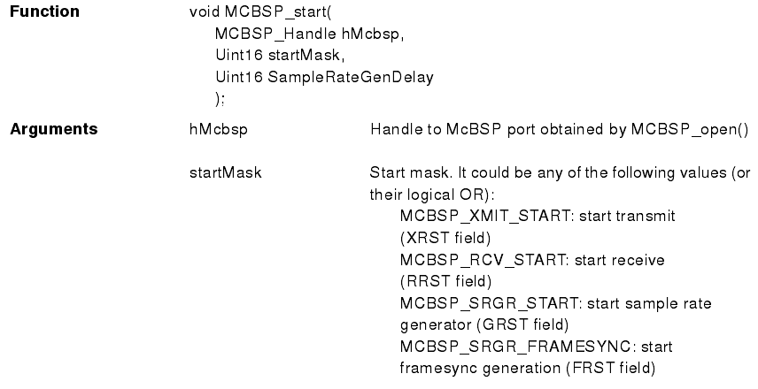
Q3: What's the function of the OR in the MCBSP_start ?
MCBSP_start ( hMcbsp,
MCBSP_RCV_START | MCBSP_XMIT_START,
0);
Regards,
Yangmm
