This thread has been locked.

If you have a related question, please click the "Ask a related question" button in the top right corner. The newly created question will be automatically linked to this question.

Optimizing AM335x IO Power in DeepSleep0

Other Parts Discussed in Thread: TPS65910, TPS65217, TPS51200, TLV320AIC26, STRIKE, TPS65910A

When using the spreadsheet from http://processors.wiki.ti.com/index.php/Optimizing_AM335x_IO_Power_in_DeepSleep0

If the pinmux is set to gpio (MUX_MODE7) and it says the DeepPad state is OUTPUT LOW.  Does that mean it will ignore the PIN_INPUT part of the pinmux? 

If Pinmux Change is required how do I determine which mux mode to change it to?  Especially if pinmux is already gpio...

If the pinmux is set to gpio and the spreadsheet claims the DeepPad state is OUTPUT LOW, should I set the sleep pinmux to PIN_OUTPUT?

  • Jonathan Cormier said:
    It was my understanding that the CKE pulldown was required and not simply recommended? It should probably be explicitly mentioned that the data manual shows the CKE with pullup which is not good.

    I'm glad you mentioned this as I had a mistake on the page.  The data manual is correct.  In short you should either have "nothing" or in the case where you have VTT termination you would have this pulled to VTT.  I removed that bullet altogether since this is already covered by the "follow the data manual" bullet.  Sorry for the confusion. Thanks for catching my mistake!

    Jonathan Cormier said:
    Could use a short section mentioning the built in VTT-toggle support in SDK 1 and 2, (using the evm-sk.dts as reference?). And in PSP11 3.2 kernel the VTT_toggle gpio is hardcoded to GPIO0_7 in sleep33xx.S line: 262. Though it uses the evm_id to enable this feature.

    Added!  It's a bit rough around the edges, but we can evolve/improve over time.  Great suggestion.

    Jonathan Cormier said:
    Since most 335x designs probably make use of the TPS65910 or TPS65217.  It may be worth discussing putting them into SLEEP mode.  I'm assuming the TPS65217 has a similar SLEEP mode to the TPS65910.

    You're right.  I actually need to learn a bit more about this myself...  I'll come back to this one.  Great suggestion.  I added a placeholder on the wiki page with some very very minimal info.

    Jonathan Cormier said:
    Also some mention of the 24Mhz crystal and how there is no way to disable a chip oscillator. Increases power usage by ~20mW on our board.

    Thanks, added!  I added it here too (hopefully to catch people at the start of designs):

    http://processors.wiki.ti.com/index.php/AM335x_Schematic_Checklist#Low_Power_considerations

    Jonathan Cormier said:
    Also a mention of the DDR_PHY_CTRL_1[20] reg_phy_enable_dynamic_pwrdn

    You're right!  I hadn't quite gotten there yet, but I added "things to check".  I have a few other things I'll likely be adding but need to do a bit more checking first.

    FYI, pretty much all the things I mention with regard to the ioctrl registers are currently incorrect in the latest code (and perhaps a couple revisions?!).  I'm working with the software team to get this updated.  I suspect this is what's breaking your board...

    Jonathan Cormier said:
    A mention of the JTAG being disabled in the 3.14 kernel. Mentioned at bottom of this page. processors.wiki.ti.com/.../AM335x_Clock_Tree_Tool

    I made some updates to my scripts to use the DAP_M3 instead of the DAP_DEBUGSS.  In my testing I no longer found it necessary to do anything special, though I have not gone back specifically to check SDK 7.00.  Have you tried it without doing anything special?  With the latest dss files I don't think it's necessary.  Please confirm.

    Jonathan Cormier said:

    Another great suggestion!  I added an "Other Resources" section to the bottom with this and a few other of my "favorites".

  • Brad Griffis said:
    Jonathan Cormier
    It was my understanding that the CKE pulldown was required and not simply recommended? It should probably be explicitly mentioned that the data manual shows the CKE with pullup which is not good.

    I'm glad you mentioned this as I had a mistake on the page.  The data manual is correct.  In short you should either have "nothing" or in the case where you have VTT termination you would have this pulled to VTT.  I removed that bullet altogether since this is already covered by the "follow the data manual" bullet.  Sorry for the confusion. Thanks for catching my mistake!

    Hmm alright, I currently had as one of my mods to take away the CKE pullup to VTT and change it to a pulldown.  I'll have to test whether it works if I leave it as is. 

    Btw your Schematic Checklist page states the following "do not connect DDR_RESET or DDR_CKE to VTT termination resistors. These should be connected directly between AM335x and DDR."

    Brad Griffis said:
    Jonathan Cormier
    Also some mention of the 24Mhz crystal and how there is no way to disable a chip oscillator. Increases power usage by ~20mW on our board.

    Thanks, added!  I added it here too (hopefully to catch people at the start of designs):

    http://processors.wiki.ti.com/index.php/AM335x_Schematic_Checklist#Low_Power_considerations

    Talking with the hardware guys, they remember changing to the oscillator due to a recommendation from TI due to some noise? issues with using the crystal and are hesitant to switch back without further information.  Any thoughts?

    Brad Griffis said:
    Jonathan Cormier
    Also a mention of the DDR_PHY_CTRL_1[20] reg_phy_enable_dynamic_pwrdn

    You're right!  I hadn't quite gotten there yet, but I added "things to check".  I have a few other things I'll likely be adding but need to do a bit more checking first.

    FYI, pretty much all the things I mention with regard to the ioctrl registers are currently incorrect in the latest code (and perhaps a couple revisions?!).  I'm working with the software team to get this updated.  I suspect this is what's breaking your board...

    Alright should be interesting to see what you come up with.

    Brad Griffis said:
    Jonathan Cormier
    A mention of the JTAG being disabled in the 3.14 kernel. Mentioned at bottom of this page. processors.wiki.ti.com/.../AM335x_Clock_Tree_Tool

    I made some updates to my scripts to use the DAP_M3 instead of the DAP_DEBUGSS.  In my testing I no longer found it necessary to do anything special, though I have not gone back specifically to check SDK 7.00.  Have you tried it without doing anything special?  With the latest dss files I don't think it's necessary.  Please confirm.

    Considering the bug prevents debugging the ARM, it probably should be mentioned.  In this context in case they want to debug the sleep33xx.S code.
       
    The patch says the following which makes it seem pretty important.
      During boot, when hwmod tries to cut clocks for debugss it always gets stuck in transition state and throws the following warning:
        
        [    0.139581 ] omap_hwmod: debugss: _wait_target_disable failed
        
        As per the information provided by folks, clocks to debugss cannot be cut.
        So adding HWMOD_INIT_NO_IDLE flag to debugss hwmod.

  • Jonathan Cormier said:
    Brad Griffis
    Jonathan Cormier
    It was my understanding that the CKE pulldown was required and not simply recommended? It should probably be explicitly mentioned that the data manual shows the CKE with pullup which is not good.

    I'm glad you mentioned this as I had a mistake on the page.  The data manual is correct.  In short you should either have "nothing" or in the case where you have VTT termination you would have this pulled to VTT.  I removed that bullet altogether since this is already covered by the "follow the data manual" bullet.  Sorry for the confusion. Thanks for catching my mistake!

    Hmm alright, I currently had as one of my mods to take away the CKE pullup to VTT and change it to a pulldown.  I'll have to test whether it works if I leave it as is. 

    If I mentioned to pull down CKE, I don't think that's correct.  One possible place of confusion is that during suspend an internal pull-down is activated on the CKE line.  It's possible you mis-took my comment about the internal pull-down as being external.  In fact, that was how I goofed the recommendation in the first place!

    The main options here are "direct connect" or "pull to VTT".  The data sheet shows that for configurations with VTT that the CKE signal should be pulled to VTT.  As a general recommendation that is correct.  However, it has been observed in specific scenarios that customers using the AM335x with the TPS51200 have actually seen a glitch on CKE related to the active discharge feature when the TPS51200 is disabled.  So this particular recommendation (of not terminating CKE) has more to do with the TPS51200 than it does the AM335x.  I've requested my colleague to please update the schematic checklist with additional background/clarification on that issue.

    On a related note, why is it that you're using two 8-bit memories instead of a single 16-bit memory?  Initially I assumed you could not get up to 1GB of memory in a x16 device (as was the case a year or so ago when I looked), but now it looks like even 2GB of DDR3 is available in a x16 package (though 1GB is the max for AM335x)!  Unless there is some major difference in the cost of the memories, I would venture to guess you could save yourself some cost by using a single x16 memory and getting rid of all the VTT logic.  That would simplify your hardware design and save cost.  Generally speaking, I find designs using VTT have a lot more issues than the designs that do a simple point-to-point connection.  This is a good case in point!  ;-)

    Jonathan Cormier said:
    Talking with the hardware guys, they remember changing to the oscillator due to a recommendation from TI due to some noise? issues with using the crystal and are hesitant to switch back without further information.  Any thoughts?

    This is the topic of Advisory 1.0.30 OSC0 and OSC1: Noise Immunity Improved When Crystal Circuit is Connected Directly to PCB Digital Ground.  The workaround is simple:

    • Connect the VSS_OSC and VSS_RTC terminals and respective crystal circuit
      component grounds directly to the nearest PCB digital ground, making it more difficult for
      noise to couple into the crystal circuit.

    Jonathan Cormier said:
    Alright should be interesting to see what you come up with.

    Things are moving quickly.  I already received a first patch from the software team.  I provided some feedback and I'm awaiting the next rev.  Would you like me to post the minimally tested version or do you want to wait until it has gone through more testing?  (Personally I would love to see the impact to your system if you're willing to "beta test".)

  • Brad Griffis said:
    Jonathan Cormier
    Hmm alright, I currently had as one of my mods to take away the CKE pullup to VTT and change it to a pulldown.  I'll have to test whether it works if I leave it as is. 

    If I mentioned to pull down CKE, I don't think that's correct.  One possible place of confusion is that during suspend an internal pull-down is activated on the CKE line.  It's possible you mis-took my comment about the internal pull-down as being external.  In fact, that was how I goofed the recommendation in the first place!

    The main options here are "direct connect" or "pull to VTT".  The data sheet shows that for configurations with VTT that the CKE signal should be pulled to VTT.  As a general recommendation that is correct.  However, it has been observed in specific scenarios that customers using the AM335x with the TPS51200 have actually seen a glitch on CKE related to the active discharge feature when the TPS51200 is disabled.  So this particular recommendation (of not terminating CKE) has more to do with the TPS51200 than it does the AM335x.  I've requested my colleague to please update the schematic checklist with additional background/clarification on that issue.

    Hmm okay still a little unclear here.  We do have a TPS51200 to control the VTT.  Does this mean we need to let it float?

    Brad Griffis said:

    On a related note, why is it that you're using two 8-bit memories instead of a single 16-bit memory?  Initially I assumed you could not get up to 1GB of memory in a x16 device (as was the case a year or so ago when I looked), but now it looks like even 2GB of DDR3 is available in a x16 package (though 1GB is the max for AM335x)!  Unless there is some major difference in the cost of the memories, I would venture to guess you could save yourself some cost by using a single x16 memory and getting rid of all the VTT logic.  That would simplify your hardware design and save cost.  Generally speaking, I find designs using VTT have a lot more issues than the designs that do a simple point-to-point connection.  This is a good case in point!  ;-)

    The module was designed several years ago and the two 8-bit memories let us do 256/512/1024 MB configurations without changing layout.  I'll bring up this possibility with the hardware team but my hunch is that changing the memory layout at this point would be too high a risk schedule wise.

    Brad Griffis said:

    This is the topic of Advisory 1.0.30 OSC0 and OSC1: Noise Immunity Improved When Crystal Circuit is Connected Directly to PCB Digital Ground.  The workaround is simple:

    • Connect the VSS_OSC and VSS_RTC terminals and respective crystal circuit
      component grounds directly to the nearest PCB digital ground, making it more difficult for
      noise to couple into the crystal circuit.

    Alright will forward this information and see how they feel about it.  Would be nice to get an easy ~20mW savings.

    Brad Griffis said:

    Things are moving quickly.  I already received a first patch from the software team.  I provided some feedback and I'm awaiting the next rev.  Would you like me to post the minimally tested version or do you want to wait until it has gone through more testing?  (Personally I would love to see the impact to your system if you're willing to "beta test".)

    Been pretty much doing beta testing this whole time trying to figure all this out so I got no problems testing something additional.

    Btw I've been playing around with the PMIC in sleep mode and found that if I disable VAUX2 my power usage during mem sleep drops to 72mW. About a 40mW drop.  This is a bit complicated though as VAUX2 apparently powers HV1, HV3, HV5, HV6 and enables two power supplies which provide power to our baseboard and are included in my power measurements.  I need to work on isolating where that power is going.  What are the repercussions of cutting power to those HVs during standby or mem?

  • Jonathan Cormier said:
    Hmm okay still a little unclear here.  We do have a TPS51200 to control the VTT.  Does this mean we need to let it float?

    The CKE pin is an output pin, so it's not floating.  It's driven by the AM335x.  Based on previous debug experience involving AM335x+TPS51200, the apps team is recommending that CKE remain "unterminated" (i.e. direct connect) for that particular configuration.

    Jonathan Cormier said:
    The module was designed several years ago and the two 8-bit memories let us do 256/512/1024 MB configurations without changing layout.  I'll bring up this possibility with the hardware team but my hunch is that changing the memory layout at this point would be too high a risk schedule wise.

    Fair enough.  I think we're just about past "the hard part".

    Jonathan Cormier said:
    Brad Griffis

    Things are moving quickly.  I already received a first patch from the software team.  I provided some feedback and I'm awaiting the next rev.  Would you like me to post the minimally tested version or do you want to wait until it has gone through more testing?  (Personally I would love to see the impact to your system if you're willing to "beta test".)

    Been pretty much doing beta testing this whole time trying to figure all this out so I got no problems testing something additional.

    I won't have a chance to do my own sanity testing until tomorrow, but I've reviewed this extensively and think it looks good:

    0001-CM3-ddr-Split-335x-and-437x-ddr-io-ctrl-handling.patch

    If possible, please apply this on top of the 0x191 firmware and try it out.  If you're game, the following feedback would be useful:

    1. Make sure you have the most up-to-date am335x-ddr-analysis.dss file.  Collect the corresponding txt output file for 3 cases:
      1. Cold boot
      2. "Almost in DS0" (i.e. halted at the while loop).
      3. After resume.  (I added a section to the wiki page called "Finish Suspend/Resume with JTAG" in case this is not clear.)
    2. Impact on power consumption during sleep.  (I really hope this saves some milliwatts!)
    3. Impact on the standby issue you were seeing.

    Jonathan Cormier said:
    Btw I've been playing around with the PMIC in sleep mode and found that if I disable VAUX2 my power usage during mem sleep drops to 72mW. About a 40mW drop.  This is a bit complicated though as VAUX2 apparently powers HV1, HV3, HV5, HV6 and enables two power supplies which provide power to our baseboard and are included in my power measurements.  I need to work on isolating where that power is going.  What are the repercussions of cutting power to those HVs during standby or mem?

    You can't cut the power to these rails.  They need to stay on.  Though given the large current consumption you're seeing on these rails it would seem that you don't have everything configured properly per the I/O spreadsheet (or something downstream is consuming excessive power).  Turning off VAUX2 is not a solution, but I think you have exposed an area for optimization in your design.  You'll need to do some further investigation.

  • PS.  I don't know if it's possible or not, but you might also consider controlling the PMIC with I2C0 on your next board spin.  That would make it easy for you to reduce your voltages during DS0.  I added this to the "low power considerations" of the schematic checklist as well.

    One other note... Regarding "validation" of the IO spreadsheet, I recommend actually using a multimeter to look at each pin during DS0 to see if the measured state agrees with your spreadsheet.  This exercise will help you find mistakes from your original entries in the spreadsheet.  If for example you see a level that doesn't match the spreadsheet (including intermediate levels), then this indicates you have something to fix within the spreadsheet and your corresponding software.  I'm going to add this info to the wiki as well.

  • Brad Griffis said:
    Jonathan Cormier
    Hmm okay still a little unclear here.  We do have a TPS51200 to control the VTT.  Does this mean we need to let it float?

    The CKE pin is an output pin, so it's not floating.  It's driven by the AM335x.  Based on previous debug experience involving AM335x+TPS51200, the apps team is recommending that CKE remain "unterminated" (i.e. direct connect) for that particular configuration.

    I removed the CKE pulldown and mem and standby still work.  There was also no noticeable change in power usage.

    This is good news since currently the two mods only involve a change during assembly to no pop these resistors. :)

    Brad Griffis said:

    I won't have a chance to do my own sanity testing until tomorrow, but I've reviewed this extensively and think it looks good:

    (Please visit the site to view this file)

    If possible, please apply this on top of the 0x191 firmware and try it out.  If you're game, the following feedback would be useful:

    1. Make sure you have the most up-to-date am335x-ddr-analysis.dss file.  Collect the corresponding txt output file for 3 cases:
      1. Cold boot
      2. "Almost in DS0" (i.e. halted at the while loop).
      3. After resume.  (I added a section to the wiki page called "Finish Suspend/Resume with JTAG" in case this is not clear.)
    2. Impact on power consumption during sleep.  (I really hope this saves some milliwatts!)
    3. Impact on the standby issue you were seeing.

    I applied your patch on the ti-v3.14.y branch since that was the one we've been using.  The only big difference between this branch and the 4.1.y branch is the " CM3: Fix GPIO wake hang on platforms using GPIO0 VTT Toggle" patch is missing from the 4.1.y branch.

    I skipped 1 for now since 2 and 3 are easier to test.

    2. Power usage  (_vtt means VTT disabled)

    Before Patch:

    • Idle: 809mW
    • standby: 136mW
    • standby_vtt: 133mW  (Broken resume)
    • mem: 113mW
    • mem_vtt: 103mW

    After patch:

    • Idle: 815mW (+6mW)
    • standby: 142mW (+6mW)
    • standby_vtt: 132mW (-1mW)
    • mem: 117mW (+4mW)
    • mem_vtt: 106mW (+3mW)

    Not sure how much variation I can expect when comparing these numbers.  But it seems there may be a slight increase in power usage.

    3. Standby appears to be working now when I disable VTT via the PMIC.

    Brad Griffis said:
    Jonathan Cormier
    Btw I've been playing around with the PMIC in sleep mode and found that if I disable VAUX2 my power usage during mem sleep drops to 72mW. About a 40mW drop.  This is a bit complicated though as VAUX2 apparently powers HV1, HV3, HV5, HV6 and enables two power supplies which provide power to our baseboard and are included in my power measurements.  I need to work on isolating where that power is going.  What are the repercussions of cutting power to those HVs during standby or mem?

    You can't cut the power to these rails.  They need to stay on.  Though given the large current consumption you're seeing on these rails it would seem that you don't have everything configured properly per the I/O spreadsheet (or something downstream is consuming excessive power).  Turning off VAUX2 is not a solution, but I think you have exposed an area for optimization in your design.  You'll need to do some further investigation.

    My guess is its something on the baseboard as it was never designed with low power in mind.  I've already found two spots where resistors were burning ~29mW of the SOMs power.

  • Brad Griffis said:

    If possible, please apply this on top of the 0x191 firmware and try it out.  If you're game, the following feedback would be useful:

    1. Make sure you have the most up-to-date am335x-ddr-analysis.dss file.  Collect the corresponding txt output file for 3 cases:
      1. Cold boot
      2. "Almost in DS0" (i.e. halted at the while loop).
      3. After resume.  (I added a section to the wiki page called "Finish Suspend/Resume with JTAG" in case this is not clear.)

  • Error during b.:

    Error reading memory: Errors during memory.readData(): Address: 0x4c000008 Error: 0x200000 (am335x-ddr-analysis2.dss#38)

    Connecting to DAP doesn't work during this stage.

    Diff between a and c:

     $ diff am335x-ddr-analysis_2015-11-11_144954.txt am335x-ddr-analysis_2015-11-11_145041.txt
    1c1
    < EMIF: SDRAM_CONFIG = 0x61c05332
    ---
    > EMIF: SDRAM_CONFIG = 0x61405332
    89c89
    < CONTROL: VTP_CTRL = 0x00010167
    ---
    > CONTROL: VTP_CTRL = 0x00000067
    

    On the second mem sleep power usage is higher and the script does run so somethings probably broken

    ddr-analysis.zip

    The following file is during the first b with the DAP JTAG code commented out.

    am335x-ddr-analysis_2015-11-11_145957_b_fix.txt
    CONTROL: DDR_CMD0_IOCTRL = 0xffe0018b
      * ddr_ba2 Weak pulldown enabled
      * ddr_wen Weak pulldown enabled
      * ddr_ba0 Weak pulldown enabled
      * ddr_a5 Weak pulldown enabled
      * ddr_ck Weak pulldown enabled
      * ddr_ckn Weak pulldown enabled
      * ddr_a3 Weak pulldown enabled
      * ddr_a4 Weak pulldown enabled
      * ddr_a8 Weak pulldown enabled
      * ddr_a9 Weak pulldown enabled
      * ddr_a6 Weak pulldown enabled
      * Bits 9:5 control ddr_ck and ddr_ckn
        - Slew slow
        - Drive Strength 9 mA
      * Bits 4:0 control ddr_ba0, ddr_ba2, ddr_wen, ddr_a[9:8], ddr_a[6:3]
        - Slew slow
        - Drive Strength 8 mA
    CONTROL: DDR_CMD1_IOCTRL = 0xffe0018b
      * ddr_a15 Weak pulldown enabled
      * ddr_a2 Weak pulldown enabled
      * ddr_a12 Weak pulldown enabled
      * ddr_a7 Weak pulldown enabled
      * ddr_ba1 Weak pulldown enabled
      * ddr_a10 Weak pulldown enabled
      * ddr_a0 Weak pulldown enabled
      * ddr_a11 Weak pulldown enabled
      * ddr_casn Weak pulldown enabled
      * ddr_rasn Weak pulldown enabled
      * Bits 4:0 control ddr_15, ddr_a[12:10], ddr_a7, ddr_a2, ddr_a0, ddr_ba1, ddr_casn, ddr_rasn
        - Slew slow
        - Drive Strength 8 mA
    CONTROL: DDR_CMD2_IOCTRL = 0xffa0098b
      * ddr_cke Weak pulldown enabled
      * ddr_resetn Weak pullup enabled
      * ddr_odt Weak pulldown enabled
      * ddr_a14 Weak pulldown enabled
      * ddr_a13 Weak pulldown enabled
      * ddr_csn0 Weak pulldown enabled
      * ddr_a1 Weak pulldown enabled
      * Bits 4:0 control ddr_cke, ddr_resetn, ddr_odt, ddr_csn0, ddr_[a14:13], ddr_a1
        - Slew slow
        - Drive Strength 8 mA
    CONTROL: DDR_DATA0_IOCTRL = 0x3ff00003
      * ddr_d8 Weak pulldown enabled
      * ddr_d9 Weak pulldown enabled
      * ddr_d10 Weak pulldown enabled
      * ddr_d11 Weak pulldown enabled
      * ddr_d12 Weak pulldown enabled
      * ddr_d13 Weak pulldown enabled
      * ddr_d14 Weak pulldown enabled
      * ddr_d15 Weak pulldown enabled
      * ddr_dqm1 Weak pulldown enabled
      * ddr_dqs1 and ddr_dqsn1 Weak pulldown enabled
      * Bits 9:5 control ddr_dqs1, ddr_dqsn1
        - Slew fastest
        - Drive Strength 5 mA
      * Bits 4:0 control ddr_d[15:8], ddr_dqm1
        - Slew fastest
        - Drive Strength 8 mA
    CONTROL: DDR_DATA1_IOCTRL = 0x3ff00003
      * ddr_d0 Weak pulldown enabled
      * ddr_d1 Weak pulldown enabled
      * ddr_d2 Weak pulldown enabled
      * ddr_d3 Weak pulldown enabled
      * ddr_d4 Weak pulldown enabled
      * ddr_d5 Weak pulldown enabled
      * ddr_d6 Weak pulldown enabled
      * ddr_d7 Weak pulldown enabled
      * ddr_dqm0 Weak pulldown enabled
      * ddr_dqs0 and ddr_dqsn0 Weak pulldown enabled
      * Bits 9:5 control ddr_dqs0, ddr_dqsn0
        - Slew fastest
        - Drive Strength 5 mA
      * Bits 4:0 control ddr_d[7:0], dqm0
        - Slew fastest
        - Drive Strength 8 mA
    CONTROL: DDR_IO_CTRL = 0x80000000
      * Bit 31: Overriding DDR_RESETn (expected for DS0).
      * Bit 28 (mddr_sel) configured for SSTL, i.e. DDR2/DDR3/DDR3L operation.
    CONTROL: VTP_CTRL = 0x00000000
      * VTP disabled (expected in DS0).
    CONTROL: VREF_CTRL = 0x00000000
      * VREF supplied externally (typical).
    CONTROL: DDR_CKE_CTRL = 0x00000001
      * CKE controlled by EMIF (normal/ungated operation).
    

    To allow the AM335x to suspend all the way, you simply change the memory location shown above to zero, and then click the "Run" icon. You'll get a "disconnect" error because the JTAG connection will be lost at that point (expected). You should be able to resume as usual at this point, e.g. press a key on the console, etc.

    Instead of clicking "Run" I've been clicking "Terminate" as it avoids the disconnect error and CCS tended to hang/crash after the disconnect error.

  • Jonathan Cormier said:

    Error during b.:

    Error reading memory: Errors during memory.readData(): Address: 0x4c000008 Error: 0x200000 (am335x-ddr-analysis2.dss#38)

    Connecting to DAP doesn't work during this stage.

    I added some notes on the page that you can execute "devmem2 0x44e00414 w 0x12500002" from the console to enable the DEBUGSS clock per your earlier comments.  This particular issue is actually because the EMIF clock is disabled while you're trying to read the EMIF registers.  I just updated the am335x-ddr-analysis.dss script with some extra try/catch statements so that I can limp past these errors and still read the rest of the registers.  Can you please update your script and try it again?

    Jonathan Cormier said:
    < CONTROL: VTP_CTRL = 0x00010167 --- > CONTROL: VTP_CTRL = 0x00000067

    My very first power up showed the values you initially reported, but even after subsequent boots I saw the second value.  I think that might just be due to the board heating up or something.

  • Can you give another update as to the current status?  I see some conflicting data points as to whether suspend is broken or not.

  • Brad Griffis said:

    One other note... Regarding "validation" of the IO spreadsheet, I recommend actually using a multimeter to look at each pin during DS0 to see if the measured state agrees with your spreadsheet.  This exercise will help you find mistakes from your original entries in the spreadsheet.  If for example you see a level that doesn't match the spreadsheet (including intermediate levels), then this indicates you have something to fix within the spreadsheet and your corresponding software.  I'm going to add this info to the wiki as well.

    This advice has proven to be very helpful so far.  Just finished probing all the pins and there are definitely some that are still in conflict.  One noteworthy conflict is the TLV320aic26 which is still driving several clocks into the ARM even during standby which is likely fighting some of the pulldowns.

    Still need to go through all the voltages measured and compare them to the expected levels. And then change pinmuxes.  One note, is that this process would have been a quicker if the PadConf spreadsheet had been either editable or copyable.  If I had been able to write the voltages directly into the spreadsheet in column U it would make it easier to compare.  As it stands I had to manually copy Pin Count, Pad State, and Pull Settings into another spreadsheet and then keep cross referencing Terminal Names as I went through measuring points.

    If we aren't putting GPIO0 into sleep, does that mean its deep sleep state doesn't apply?  For example GPIO0[20] isn't connected to anything and the spreadsheet says it should be output low but I measured about 0.1V which seems likely that its floating.  This should be mentioned in your guide.

    Brad Griffis said:

    Can you give another update as to the current status?  I see some conflicting data points as to whether suspend is broken or not.

    I have not seen any problems resuming from Standby with your CM3 patch when VTT is disabled.  The only negative was the ~6mW power increase.

  • Jonathan Cormier said:
    One noteworthy conflict is the TLV320aic26 which is still driving several clocks into the ARM even during standby which is likely fighting some of the pulldowns.

    I just had a quick look at the AIC26 data manual.  There's a /PWD pin for power-down (though that pin can be repurposed as something else).  Do you know if your design keeps that as a power-down pin?  If so, you should set the state of the corresponding I/O to pull that low.  I expect the AIC26 should not be clocking anything in its low power mode.  I imagine the power of the AIC26 (i.e. doing conversions, etc.) is much more power than even the contention on the pins.

    Jonathan Cormier said:
    One note, is that this process would have been a quicker if the PadConf spreadsheet had been either editable or copyable.

    I agree with you and have requested that the spreadsheet maintainer add a column where you can record voltages.

    Jonathan Cormier said:
    If we aren't putting GPIO0 into sleep, does that mean its deep sleep state doesn't apply?

    Correct. This is another thing I requested the maintainer to try and address though it might be too difficult.  Ideally we can fix it in the spreadsheet itself.  If not, I'll add some notes.

    Jonathan Cormier said:
    I have not seen any problems resuming from Standby with your CM3 patch when VTT is disabled.  The only negative was the ~6mW power increase.

    Are you saying:

    • Leaving VTT enabled all the time works fine, but results in an additional 6mW of power consumption during standby.
    • Dynamically disabling/re-enabling VTT does not work for standby (but it works for DS0)?

  • Brad Griffis said:
    Jonathan Cormier
    One noteworthy conflict is the TLV320aic26 which is still driving several clocks into the ARM even during standby which is likely fighting some of the pulldowns.

    I just had a quick look at the AIC26 data manual.  There's a /PWD pin for power-down (though that pin can be repurposed as something else).  Do you know if your design keeps that as a power-down pin?  If so, you should set the state of the corresponding I/O to pull that low.  I expect the AIC26 should not be clocking anything in its low power mode.  I imagine the power of the AIC26 (i.e. doing conversions, etc.) is much more power than even the contention on the pins.

    Sorry this is where things get a little complicated.  I'm using a development kit in order to investigate the power usage of our SOM.  The devkit was never intended for low power.  We are going to be doing a custom baseboard design for lower power.  All of my power measurements have been intending to ignore the power usage of the devkit and only include power used by the SOM.  So the fact that the AIC isn't sleeping shouldn't be directly showing up in my measurements but the clocks its driving could be affecting my power draw.  For the purpose of this experiment I may just have them pull the AIC26 off the devkit since it won't be on the custom design.

    Brad Griffis said:
    Jonathan Cormier
    One note, is that this process would have been a quicker if the PadConf spreadsheet had been either editable or copyable.

    I agree with you and have requested that the spreadsheet maintainer add a column where you can record voltages.

    Perhaps just don't lock all U and up columns?

    Brad Griffis said:
    Jonathan Cormier
    I have not seen any problems resuming from Standby with your CM3 patch when VTT is disabled.  The only negative was the ~6mW power increase.

    Are you saying:

    • Leaving VTT enabled all the time works fine, but results in an additional 6mW of power consumption during standby.
    • Dynamically disabling/re-enabling VTT does not work for standby (but it works for DS0)?

    What your describing above fits the state before your patch, except having VTT enabled all the time was closer to an additional 12mw.

    After the patch, I am able to disable the VTT during standby and resume without issue.  So the patch is helping.

    The power increase was refering to the following measurements i posted.

    Jonathan Cormier said:

    2. Power usage  (_vtt means VTT disabled)

    Before Patch:

    • Idle: 809mW
    • standby: 136mW
    • standby_vtt: 133mW  (Broken resume)
    • mem: 113mW
    • mem_vtt: 103mW

    After patch:

    • Idle: 815mW (+6mW)
    • standby: 142mW (+6mW)
    • standby_vtt: 132mW (-1mW)
    • mem: 117mW (+4mW)
    • mem_vtt: 106mW (+3mW)

  • Brad Griffis said:
    Jonathan Cormier
    If we aren't putting GPIO0 into sleep, does that mean its deep sleep state doesn't apply?

    Correct. This is another thing I requested the maintainer to try and address though it might be too difficult.  Ideally we can fix it in the spreadsheet itself.  If not, I'll add some notes.

    Is the deep sleep state for gpio0 pins disabled even if there pinmux isn't set to gpio or does that only apply when pinmuxed to gpio?

  • It's specific to the mux mode, not the pin.
  • I updated the pinmuxes and verified the pins that were at odd voltages now have better voltage levels.  Unfortunately there wasn't a change in power usage.


    I then had the AIC26 PWD pulled low in hardware as well as disabling the 24Mhz Audio sysclk.  Power usage dropped by 15mW. So currently at ~92mW.

  • Reduced power usage by another 16mW by disabling the power LED on our SOM. We are currently at 76mW during mem sleep. Which if you include the 20mW we are burning via the oscillator that brings up down to ~56mW.
  • Can you run another quick test for me? You'll need your special "jtag stop" firmware in order to poke a register just before you hit DS0. Here's the procedure:

    1. Initiate DS0, e.g. "echo mem > /sys/power/state"
    2. Connect to the M3.
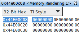
    3. In the memory window go to 0x44E00C0C. (I see a value of 0x0E000061 in mine.)
    4. Write the value 0x06000070 into there instead. (The register before it at 0x44E00C08 should hopefully become zero when you do this.)
    5. Type in "SP" for the memory address and change the second 32-bit value from 1->0 to make stop=0.
    6. Disconnect.

    What's the power consumption while you're asleep in this scenario?

    Does this create any problems, i.e. it doesn't crash the board or anything right?
  • Brad Griffis said:
    Can you run another quick test for me? You'll need your special "jtag stop" firmware in order to poke a register just before you hit DS0. Here's the procedure:

    1. Initiate DS0, e.g. "echo mem > /sys/power/state"
    2. Connect to the M3.
    3. In the memory window go to 0x44E00C0C. (I see a value of 0x0E000061 in mine.)
    4. Write the value 0x06000070 into there instead. (The register before it at 0x44E00C08 should hopefully become zero when you do this.)
    5. Type in "SP" for the memory address and change the second 32-bit value from 1->0 to make stop=0.
    6. Disconnect.

    What's the power consumption while you're asleep in this scenario?

    Does this create any problems, i.e. it doesn't crash the board or anything right?

    Power usage during mem was ~75.7mW.  Not marginally different to power usage without change ~76.2mW.

    Was unable to resume after this register change.  Power levels came back up but console didn't respond.

    Tested this twice with same results.

    Registers before

    Registers after

  • Well that's disappointing on both fronts!  I was hoping for a more substantial power reduction, and I was not expecting it to cause any stability issues.  (Though this might be why it's the way it is in the first place!)

    Before I completely give up on this idea, would you please humor and try this one more time.  Here are a couple binaries I just made.  Both of them have the ioctrl changes from yesterday that fixed your standby issue.  (Though we're testing "mem" now, just so we're on the same page.)  Additionally, I updated the code so that it should transition the PER domain to OFF (rather than RET) without the need for you to poke registers through the JTAG window.  I have two versions: one with the spin loop and one without: <files-removed: bad idea!>

    Would you mind trying the version without the spin loop and testing it out?  In particular, I'm wondering if you don't ever connect with JTAG does it work any better.

    I tested this code on both a BeagleBone Black as well as a AM335x EVM.  It worked fine on both.  So I'm a bit surprised it's not working on your board.  I through the version with the spin loop in there too in case you want to take a look at things close to suspend.
     

  • Failed to load on the 3.14 kernel.

    [ 3.180723] remoteproc0: powering up wkup_m3
    [ 3.186400] remoteproc0: Booting fw image am335x-pm-firmware.elf, size 220574
    [ 3.194207] remoteproc0: erroneous trace resource entry
    [ 3.199833] remoteproc0: Failed to process resources: -22
    [ 3.205671] wkup_m3 44d00000.wkup_m3: rproc_boot failed
  • Oops! I'm testing on the 4.1 kernel (which you cannot get booted per your other thread). The firmware are not compatible. :-(

    If you're interested in trying it out, here's what I did:

    diff --git a/src/pm_services/pm_state_data.c b/src/pm_services/pm_state_data.c
    index c04f4d8..3b91f6a 100644
    --- a/src/pm_services/pm_state_data.c
    +++ b/src/pm_services/pm_state_data.c
    @@ -31,10 +31,10 @@ union state_data ds0_data = {
    .pd_mpu_l1_ret_state = MEM_BANK_RET_ST_OFF,
    .pd_mpu_l2_ret_state = MEM_BANK_RET_ST_OFF,

    - .pd_per_state = PD_RET,
    + .pd_per_state = PD_OFF,
    .pd_per_icss_mem_ret_state = MEM_BANK_RET_ST_OFF,
    .pd_per_mem_ret_state = MEM_BANK_RET_ST_OFF,
    - .pd_per_ocmc_ret_state = MEM_BANK_RET_ST_RET,
    + .pd_per_ocmc_ret_state = MEM_BANK_RET_ST_OFF,
    .pd_per_ocmc2_ret_state = MEM_BANK_RET_ST_OFF,

    .wake_sources = WAKE_ALL,


    EDIT: Don't bother with this for the reasons outlined in my next post!

  • Jonathan,

    Nevermind on my idea here. It's a waste of time. The software team educated me why on this particular piece of the code is already correct. The Linux resume handler is located in the OCMC RAM so we cannot power down that RAM! Putting the PD_PER domain in "RET" will have the effect of powering off all logic, but selectively retaining memory (in this case we are only retaining OCMC). So don't spend any more time pursuing it. In fact, I'm going to strike out some of my comments from the last couple posts since I seem to have gotten off track.

    Brad
  • Alright no problem.
  • I created some patches to enable sleep mode for the tps65910 in the kernel. Does TI have a mailing list for their 3.14/4.1 kernel?
  • FYI, I have spent many hours trying to make my scripts more robust. In particular, I was able to manage to put in some logic such that the nagging issue related to SDK 7.00 and later is ancient history. Specifically, I noticed that even with SDK 7.00 I was always able to connect to the M3 (and DAP_M3). And from the DAP_M3 I was able to adjust the register where the issue existed. So now my scripts always connect to the DAP_M3 first and then enable the DEBUGSS clock if it is disabled. I restore the state of the register at the end so as to not change the state of the system. Also, in the case where the EMIF is disabled (e.g. when you're nearly in DS0), I have a more graceful message that prints out. So please download the updated scripts!

    Also, I have a new script (documented on the suspend/resume wiki page) for the case where not all domains have transitioned (i.e. to track down the offending module). I don't think this is relevant for your scenario but I thought I would pass it on. I appreciate the feedback you've been giving. I've made quite a few more updates to the wiki page as well.

    As a next step, if you're able to get any further refinements with regard to your power consumption, that would still likely help further track down where you're burning power. I think I'm about at the end of what I can do over a forum. I have very much appreciated your feedback regarding the scripts, the wiki page, etc.
  • Jonathan Cormier said:
    I created some patches to enable sleep mode for the tps65910in the kernel. Does TI have a mailing list for their 3.14/4.1 kernel?

    As a general matter new patches generally should be sent upstream and applied against mainline.  Though if you would like to make a quick and easy contribution you might start a brand new thread and just attach the patches, specifying what SDK they apply against.

    Is that something you found reduced power even further?  My goal for the wiki page was to attach random patches that were known to improve power.  I haven't really gotten around to it yet though, so I have so far only attached the one patch I mentioned earlier for SDK 6.00.  Perhaps post them here or in a new thread and we can take it from there.

    It's way too late on Friday so I'm rambling.  Time to get out of here!  :-)

  • Brad Griffis said:
    Jonathan Cormier
    I created some patches to enable sleep mode for the tps65910in the kernel. Does TI have a mailing list for their 3.14/4.1 kernel?

    As a general matter new patches generally should be sent upstream and applied against mainline.  Though if you would like to make a quick and easy contribution you might start a brand new thread and just attach the patches, specifying what SDK they apply against.

    Is that something you found reduced power even further?  My goal for the wiki page was to attach random patches that were known to improve power.  I haven't really gotten around to it yet though, so I have so far only attached the one patch I mentioned earlier for SDK 6.00.  Perhaps post them here or in a new thread and we can take it from there.

    It's way too late on Friday so I'm rambling.  Time to get out of here!  :-)

    The TPS65910 has a pin called SLEEP which when enabled and pulled low puts the PMIC into a lower powered state.  Since I'm measuring power usage at the input of the PMIC this means its power usage contributes to my readings.  I see ~40mW power savings by putting the PMIC into its sleep state.  On top of this the PMIC can be configured to power off power rails when it enters sleep. So I have it configured to disable VDIG1 which is wired to the VTT enable.

    I was setting this all up using i2cget and i2cset.  So the patches allow this configuration to be done through device tree.  Most of the support was already there but had never been updated to allow access via device tree.

    Attaching patches but if I get some chance I'll likely also submit to mailing lists.  TPS code hasn't changed much between 3.14 and 4.1 so should apply to both.


    0001-mfd-tps65910-Add-device-tree-support-for-SLEEP-state.patch.txt
    From dafd326f0b844454accf52fe85858dbb394d47e7 Mon Sep 17 00:00:00 2001
    From: "Cormier, Jonathan" <jcormier@criticallink.com>
    Date: Fri, 13 Nov 2015 15:51:47 -0500
    Subject: [PATCH 1/3] mfd: tps65910: Add device tree support for SLEEP state
    
    ---
     Documentation/devicetree/bindings/mfd/tps65910.txt |  4 ++++
     drivers/mfd/tps65910.c                             | 22 ++++++++++++++++++++++
     2 files changed, 26 insertions(+)
    
    diff --git a/Documentation/devicetree/bindings/mfd/tps65910.txt b/Documentation/devicetree/bindings/mfd/tps65910.txt
    index b4bd98af1cc7..5a80a90b7d7e 100644
    --- a/Documentation/devicetree/bindings/mfd/tps65910.txt
    +++ b/Documentation/devicetree/bindings/mfd/tps65910.txt
    @@ -61,6 +61,10 @@ Optional properties:
       There should be 9 entries here, one for each gpio.
     - ti,system-power-controller: Telling whether or not this pmic is controlling
       the system power.
    +- ti,en-dev-sleep: allows SLEEP device state. To enter SLEEP state this must be enabled, DEV_OFF and DEV_OFF_RST must be 0, interrupt registers must be cleared, and SLEEP pin must be active.
    +- ti,sleep-therm-keepon: thermal monitoring is maintained during device SLEEP state
    +- ti,sleep-clkout32k-keepon: CLK32KOUT output is maintained during device SLEEP state
    +- ti,sleep-i2chs-keepon: high speed internal clock is maintained during device SLEEP state
     
     Regulator Optional properties:
     - ti,regulator-ext-sleep-control: enable external sleep
    diff --git a/drivers/mfd/tps65910.c b/drivers/mfd/tps65910.c
    index d6573318977f..05a6a62643ee 100644
    --- a/drivers/mfd/tps65910.c
    +++ b/drivers/mfd/tps65910.c
    @@ -421,6 +421,28 @@ static struct tps65910_board *tps65910_parse_dt(struct i2c_client *client,
     	prop = of_property_read_bool(np, "ti,en-ck32k-xtal");
     	board_info->en_ck32k_xtal = prop;
     
    +	prop = of_property_read_bool(np, "ti,en-dev-sleep");
    +	board_info->en_dev_slp = prop;
    +
    +	if(board_info->en_dev_slp)
    +	{
    +		board_info->slp_keepon = devm_kzalloc(&client->dev, sizeof(*board_info->slp_keepon),
    +				GFP_KERNEL);
    +		if (!board_info->slp_keepon) {
    +			dev_err(&client->dev, "Failed to allocate slp_keepon\n");
    +			return NULL;
    +		}
    +
    +		prop = of_property_read_bool(np, "ti,sleep-therm-keepon");
    +		board_info->slp_keepon->therm_keepon = prop;
    +
    +		prop = of_property_read_bool(np, "ti,sleep-clkout32k-keepon");
    +		board_info->slp_keepon->clkout32k_keepon = prop;
    +
    +		prop = of_property_read_bool(np, "ti,sleep-i2chs-keepon");
    +		board_info->slp_keepon->i2chs_keepon = prop;
    +	}
    +
     	board_info->irq = client->irq;
     	board_info->irq_base = -1;
     	board_info->pm_off = of_property_read_bool(np,
    -- 
    1.9.1


    0002-mtd-tps65910-Add-sleep-mode-fix-to-clear-interrupts-.patch.txt
    From 2371ef9bbcffc6b2b27fdf754b55c8072a105a59 Mon Sep 17 00:00:00 2001
    From: "Cormier, Jonathan" <jcormier@criticallink.com>
    Date: Fri, 13 Nov 2015 15:39:12 -0500
    Subject: [PATCH 2/3] mtd: tps65910: Add sleep mode fix to clear interrupts
     when irq not used.
    
    The PMIC won't enter sleep mode if an interrupt is pending. In the case where
    the interrupt isn't connected and thus isn't configured, the IRQ registration
    will fail and the interrupt registers will not get acknowledged. The solution
    is to clear the interrupts and then mask the interrupts.
    ---
     drivers/mfd/tps65910.c | 34 +++++++++++++++++++++++++++++++++-
     1 file changed, 33 insertions(+), 1 deletion(-)
    
    diff --git a/drivers/mfd/tps65910.c b/drivers/mfd/tps65910.c
    index 05a6a62643ee..7bd041ba14d2 100644
    --- a/drivers/mfd/tps65910.c
    +++ b/drivers/mfd/tps65910.c
    @@ -518,10 +518,42 @@ static int tps65910_i2c_probe(struct i2c_client *i2c,
     	init_data->irq = pmic_plat_data->irq;
     	init_data->irq_base = pmic_plat_data->irq_base;
     
    -	tps65910_irq_init(tps65910, init_data->irq, init_data);
    +	ret = tps65910_irq_init(tps65910, init_data->irq, init_data);
     	tps65910_ck32k_init(tps65910, pmic_plat_data);
     	tps65910_sleepinit(tps65910, pmic_plat_data);
     
    +	/* If irqs aren't enabled and sleep mode is enabled we need to clear/mask interrupt registers */
    +	/* Sleep mode won't be entered if an interrupt is pending */
    +	if (ret < 0 && pmic_plat_data->en_dev_slp)
    +		ret = tps65910_reg_set_bits(tps65910,
    +				TPS65910_INT_STS,
    +				0xFF); {
    +		if (ret < 0) {
    +			dev_err(&i2c->dev, "clear interrupt regs failed: %d\n", ret);
    +		}
    +
    +		ret = tps65910_reg_set_bits(tps65910,
    +				TPS65910_INT_MSK,
    +				0xFF);
    +		if (ret < 0) {
    +			dev_err(&i2c->dev, "mask interrupt regs failed: %d\n", ret);
    +		}
    +
    +		ret = tps65910_reg_set_bits(tps65910,
    +				TPS65910_INT_STS2,
    +				0xFF);
    +		if (ret < 0) {
    +			dev_err(&i2c->dev, "clear interrupt 2 regs failed: %d\n", ret);
    +		}
    +
    +		ret = tps65910_reg_set_bits(tps65910,
    +				TPS65910_INT_MSK2,
    +				0xFF);
    +		if (ret < 0) {
    +			dev_err(&i2c->dev, "mask interrupt 2 regs failed: %d\n", ret);
    +		}
    +	}
    +
     	if (pmic_plat_data->pm_off && !pm_power_off) {
     		tps65910_i2c_client = i2c;
     		pm_power_off = tps65910_power_off;
    -- 
    1.9.1


    Apparently .patch isn't a accepted filetype...

  • Brad Griffis said:

    FYI, I have spent many hours trying to make my scripts more robust. In particular, I was able to manage to put in some logic such that the nagging issue related to SDK 7.00 and later is ancient history. Specifically, I noticed that even with SDK 7.00 I was always able to connect to the M3 (and DAP_M3). And from the DAP_M3 I was able to adjust the register where the issue existed. So now my scripts always connect to the DAP_M3 first and then enable the DEBUGSS clock if it is disabled. I restore the state of the register at the end so as to not change the state of the system. Also, in the case where the EMIF is disabled (e.g. when you're nearly in DS0), I have a more graceful message that prints out. So please download the updated scripts!

    Cool.  Any idea if there is any benefit to leaving the DEBUGSS clock disabled.  The patch seemed to indicate that having the DEBUGSS clock disabled was a invalid state.

    Brad Griffis said:


    As a next step, if you're able to get any further refinements with regard to your power consumption, that would still likely help further track down where you're burning power. I think I'm about at the end of what I can do over a forum. I have very much appreciated your feedback regarding the scripts, the wiki page, etc.

    Yes thanks for all the help.  We are currently within our power budget and are planning on putting the power investigation on hold until we get the custom baseboard for this project.

  • Jonathan Cormier said:
    Cool.  Any idea if there is any benefit to leaving the DEBUGSS clock disabled.  The patch seemed to indicate that having the DEBUGSS clock disabled was a invalid state.

    Seems like you have a pretty good power measurement setup. (Better than mine!)  A simple test would be:

    1. Take a measurement.
    2. Execute "devmem2 0x44e00414 w 0x12500002" and then take another measurement.

    Jonathan Cormier said:
    We are currently within our power budget and are planning on putting the power investigation on hold until we get the custom baseboard for this project.

    Ok, thanks for the update.

  • Jonathan Cormier said:
    The TPS65910 has a pin called SLEEP which when enabled and pulled low puts the PMIC into a lower powered state.  Since I'm measuring power usage at the input of the PMIC this means its power usage contributes to my readings.  I see ~40mW power savings by putting the PMIC into its sleep state.  On top of this the PMIC can be configured to power off power rails when it enters sleep. So I have it configured to disable VDIG1 which is wired to the VTT enable.

    This is a great data point.  That's a huge reduction.  Are you sure that all the necessary rails are still up?

  • Brad Griffis said:
    Jonathan Cormier
    Cool.  Any idea if there is any benefit to leaving the DEBUGSS clock disabled.  The patch seemed to indicate that having the DEBUGSS clock disabled was a invalid state.

    Seems like you have a pretty good power measurement setup. (Better than mine!)  A simple test would be:

    1. Take a measurement.
    2. Execute "devmem2 0x44e00414 w 0x12500002" and then take another measurement.

    Could not detect any difference in power usage during idle or mem sleep when this clock is enabled or disabled.

    Brad Griffis said:

    This is a great data point.  That's a huge reduction.  Are you sure that all the necessary rails are still up?

    Yeah I believe so.  By default the SLEEP mode doesn't turn off any rails instead switches them to a low power state via some hardware magic :P.  There are fields that can be set to keep certain rails in high power mode and fields to disable rails entirely. Its a shame there’s no field to reduce the core voltage when in sleep but you can't have everything :P.

  • Which signal from the AM335x are you connecting to the SLEEP pin of the TPS65910A?
  • I am using GPIO0_19 (XDMA_EVENT_INTR0).
  • At what point does it turn back on? When Linux starts? It doesn't look like we are doing this on the EVM. One concern I might have is that you might see a dip on the MPU rail due to the reduced load/transient capabilities.
  • Because I'm enabling it using the vtt_toggle. Its being turned back on during the SRAM linux restore. When the VTT resistors would have been re-enabled.
  • Make sure you're also setting DCDCCTRL_REG [1:0] = 00 in the TPS65910A per its errata. It's not something you see all the time, but once you get a large number of units doing a large number of suspend/resume sequences you'll start seeing a very small number of occurrences (IF you don't implement the simple workaround!).
  • Brad Griffis said:
    Make sure you're also setting DCDCCTRL_REG [1:0] = 00 in the TPS65910A per its errata. It's not something you see all the time, but once you get a large number of units doing a large number of suspend/resume sequences you'll start seeing a very small number of occurrences (IF you don't implement the simple workaround!).

    Thanks I didn't understand the relevance of the errata when I last read it however long ago.  Created a ticket to update driver when I get back to sleep mode stuff.

  • Brad Griffis said:
    Make sure you're also setting DCDCCTRL_REG [1:0] = 00 in the TPS65910A per its errata. It's not something you see all the time, but once you get a large number of units doing a large number of suspend/resume sequences you'll start seeing a very small number of occurrences (IF you don't implement the simple workaround!).

    What are the effects of setting these bits to 0?  If I create a kernel patch for this errata would it only apply if someone enables the SLEEP pin or could they always be set to 0?

  • They can be used by anyone. The only real effect is less predictable noise relationship among switchers.
  • Jonathan Cormier said:
    One note, is that this process would have been a quicker if the PadConf spreadsheet had been either editable or copyable.  If I had been able to write the voltages directly into the spreadsheet in column U it would make it easier to compare. 

    FYI, we updated the spreadsheet yesterday to allow you to enter your measured voltages directly.  Thanks for that feedback.

  • Thanks for the update. We should be getting our custom board in after the new year so I'm sure I'll be using this again soon.