This thread has been locked.

If you have a related question, please click the "Ask a related question" button in the top right corner. The newly created question will be automatically linked to this question.

[C6748] UPP intermittently dropping data transfers?

My Universal Parallel Port (UPP) seems to be intermittently dropping incoming data transfers.  How do I fix that?

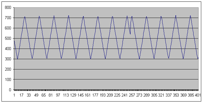
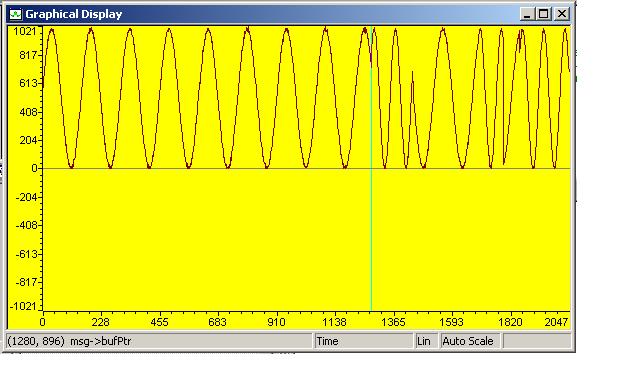
Here are the clues so far. I'm using the UPP peripheral on the C6748, LogicPD EVM board, inputting 10-bit A-to-D data sampled at 14 MHz.  The UPP acquires exactly the right number of samples -- that is, when I request N samples, it delivers exactly N samples -- however the samples are not contiguous, as some samples are missing.  For example, I input a clean analog triangle waveform, and find that occasionally 20 samples in a row are omitted (which is clearly visible when I examine the acquired data). 

I'm using only one channel of the UPP.  (However, I am compelled to put the UPP into "Dual Channel Mode" in the UPCTL register, because this affects the pinout of the C6748 and hence is compelled by the layout of the EVM board.) On the EVM board, the sampling clock comes to the UPP from the external programmable clock (the TI CDCE913PW) -- so perhaps that chip is occasionally dropping the clock pulses?  I dunno. 

I believe (perhaps incorrectly?) that the UPP has internal buffering and independent control that makes it's sampling rate quite independent of the processor interrupts, etc. So I'm baffled how to solve this problem.

Thanks for any help you can give.

  • Walter,

    What is the frequency of your triangle wave?  This other recent thread found that there is a high-pass filter on the analog components: http://e2e.ti.com/support/dsp/tms320c6000_high_performance_dsps/f/115/p/48019/171310.aspx

    -Tommy

  • Here is the data I'm getting.  The data is sampled at 13.5MegaHz, at 10-bits resolution (using the EVM UI board and baseboard).  The triangle wave is 32 samples long (or 421875 Hz).  You can see by the waveform that it is not band limited, since the triangle waves retain their shape.  Notice that (apparently) 20 samples are dropped near the 250 time mark -- this is the problem I'm trying to figure out.  The first clue I need concerns the UPP, that is, I believe (correctly, or incorrectly?) that the UPP is thoroughly robust and blameless, that it is fully buffered with its own internal memory and is immune from processor interrupts and whatever the processor is doing. In other words, the problem must be coming from some other source?  (such as the external programmable clock on the EVM board?)  I dunno.  But the first thing I want to nail down is this:  Is the UPP blameless in such things?  Have other people run across such a problem before?

  • I am having exactly the same problem that you have except my buffer is only good until 1280 bytes.  I can repeat the acquisition and the sampling buffer is always good until the 1280th bytes with any frequency that I sample.  I can vary my buffer size from 64 bytes up until 1280 bytes.  This is when the UPP starts having problem.   I have yet to figure out what wrong.


  • A couple of questions to both Walter and Kevin:

    Are you using the BIOS drivers for UPP?  Is there any other device activity taking place in the system which may be competing for resources?

    -Tommy

  • Tommy,

    I'm not using the BIOS drivers for UPP.  Instead I based my code on the LogicPD test files that came with the EVM board, (which likewise do not use the BIOS). My UPP mostly operates correctly, so I doubt it's a parameter-setup issue. 

    As for competing resources:  The main competing resource is the sampling rate itself, which is 13.5 Mega Samples per second -- so the UPP has to average 27 Megabytes per second into memory, and I'm using the off-chip memory -- memory that is off the C6748 chip, but on the C6748 SOM mini-board.  This memory is a bit slower than the on-chip memory. 

    During the sampling burst, the CPU is mostly in idle, waiting for an interrupt to pull it into action -- this leaves the UPP free to do its chores largely unhindered by the CPU.  (There are occasional interrupts, but little that should bother the UPP during its sampling burst.  For example, one type of interrupt causes the system to prematurely stop sampling and reset for the next sampling burst.  Another interrupt causes a sampling burst to begin.  And a third type of interrupt tells the processor it can now process the data.  So again, there is little to bother the UPP other than it's thrashing of memory. At least at cursory analysis would suggest that conclusion. Perhaps I am missing something?  Is there a memory bottleneck of some type?  Perhaps I could use the UPP error-flagging interrupts to detect this?)

    (Note:  My previous graph zoomed-in on the troublesome spot, which actually occurred at the 1452nd sample. )

  • Tommy and Walter,

    I finally have figured out what to do to make the UPP to work.  I use some of the example codes from LogicPD to help me config my application and also use the BIOS to do mutiltasking and data synchronization.  In my application, I have a series of buffers which I alternate and pass to the UPP descriptor 0 register to collect data and this is where the problem is.  What I find out is the address of the data buffer has to be properly aligned in memory with the lowest 3 bits address being always 0.  So a statement like this will do the job with rxBuf the address being pass to UPXD0

    #pragma DATA_ALIGN(rxBuf,8)

    and the the most important thing is the UPP "internal DMA" only likes to do its memory transfer to the same location.  So the address that got assigned to UPXDO  has not only to be aligned but fixed.  Another word I can only use a single buffer for this transfer.  If I do switch to another buffer to acquire my data then my DMA data got damaged.  The net result is the cost of time to transfer the content of this buffer to another location so the same buffer can be reused for the next acquistion.

  • Kevin,

    Your suggestion would not seem to solve my problem.  I'm already aligning the data (on a 64 byte boundary, which I presumed would make the UPP even happier, since it does memory burst transfers 64 bytes at a time):

    #pragma DATA_ALIGN (data_buffer, 64)

    Requiring UPXD0 to be fixed and unchanging would seem to be what software people jokingly call an "undocumented feature" (in other words, a bug).  I don't see it called out in the UPP manual. 

    In my case, I monitor the PEND bit until it clears, then load the UPXD0 with a different address while the first transfer burst is ongoing -- but the error shows up on the first transfer burst. Does the mere act of loading this register with a new address cause the error (at the moment it is loaded)?  Or are these two events unrelated? 

    In my case, the destination addresses are arranged contiguously, so my one incoming stream of data gets laid seemlessly across the boundary of the two transfers (with no lost data).  My understanding of the UPP manual is that the two burst transfers will occur seemlessly (without dropped data).  Am I mistaken?

  • Walter,

    It may very well be an undocumented feature.  And so far I have found a few with this EVM board package.  My buffers are also contiguous and aligned in memory, but it does not matter.  As soon as you load the UPP UPXDO register with a new address, the data in the IDMA stream is corrupted.  Initially with the example code, I tried to poll the PEND bit before and after the loading, it did not help.  The two events are unrelated.  I also tried my current method which is interrupt driven and seems to be much better when you do a large transfer, it showed the same error.  I have not understood or figured out why setting a new address would cause the IDMA to corrupt but have confirmed it with my code and the upp driver code that is developed by Joe Coombs from TI which I have used as a reference.  In his driver, the buffer address is also fixed.  You can take a look at it at this link and download the file UPP_BIOS_Driver_Install_v10.zip to see

    http://processors.wiki.ti.com/index.php/Using_the_uPP_DSP/BIOS_Driver

    Kevin.


  • Kevin,

    You seem to have discovered a substantial "undocumented feature" (wink, wink) -- a bug in the UPP.  If true, that will cause me to radically alter my software design, which I hope I don't have to do.  Rather, I hope the bug isn't actually there, and that a solution can be found.  At the outside, I will grant that possibility. 

    There is still the possibility (for example) that the bug is some strange interaction caused by the emulator (which can pause the UPP mid-stream when the UPPCR.FREE=0 & UPPCR.SOFT=1).  Or some such thing.  ... 

    And I am reluctant to charge TI with such a bug.  Am I correct in believing the UPP peripheral is not new and has been used before in many other processors, so such bugs would have been discovered long ago (if these are present)?  I hope a TI person will add some clarification to this matter.

    Meanwhile, I suppose we can monitor the status register (UPISR) in the UPP to see if the UPP itself detects any data transfer errors. 

    Thanks for your help!


  • Excellent discussion. Thank you for participating in the E2E forum.

    Please take another look at the uPP User's Guide, in particular section 2.4 "Internal DMA Controller Description". The following page in the User's Guide talks about how you program transfers, and FIgure 8 immediately makes you aware that the uPP DMA controller was designed to allow a progressive sequence of memory blocks to be accessed, which is exactly what you want to do.

    The text below Figure 8 explains the process of programming for DMA transfers. The longest paragraph, in the middle, explains how to seamlessly program sequential DMA addresses:

    SPRUGJ5b p 15 said:

    Each DMA channel allows a second descriptor to be queued while the previously programmed DMA transfer is still running. The UPxS2.PEND bit reports whether a new set of DMA parameters may be written to the DMA descriptor registers. Each DMA channel can have at most one active transfer and one queued transfer. This allows each I/O channel to perform uninterrupted, consecutive transactions across DMA transfer boundaries.

    This feature and this programming technique do require you to stay one step ahead of the uPP port. But what you have to avoid is a short gap between when one buffer transfer is completed and the very next sample being clocked. The queued transfer parameters allow you to do just that.

    Sorry that I do not have a code example for you. But you both sound very capable. Please share what you come up with.

  • RandyP,

    Thank you for joining our conversation.  Kevin and I are noticing situations where the UPP appears to be intermittently dropping data (see above screen-shots).  Kevin and I are already using your suggestion of waiting until the PEND bit clears before writing to the UPP descriptor registers -- yet the problem occurs.  We'd appreciate your input (from the TI-informed side of things).  Is this a bug in the UPP?  How can we cure the problem?

    Thanks for your help.


  • What values do you program into UPxD0-2?

    When do you test UPxS2.PEND? In an ISR (triggered by what event) or in a TSK?

    How many times do you have to test UPxS2.PEND before it is low?

  • RandyP,

    Here is the snippet from my code:

     uint32_t next_buffer;
    #define MAX_SOF_LENGTH (4120)
     UPXS2_t * UPIS2r = (UPXS2_t *)&(UPP->UPIS2)
     while(UPIS2r->bits.PEND == 1){};
     UPP->UPID0 = (uint32_t)&data_buffer;
     UPP->UPID1 = MAX_SOF_LENGTH + 0x00010000;
     UPP->UPID2 = MAX_SOF_LENGTH;
     UPP->UPIER = 0x1F1F;
     UPP->UPEOI = 0;
     next_buffer = (uint32_t)data_buffer + MAX_SOF_LENGTH;
     while(UPIS2r->bits.PEND == 1){};
     UPP->UPID0 = next_buffer;
     UPP->UPID1 = 0x0014FFC0;
     UPP->UPID2 = 0x0000FFC0;

    The "while" statement tests the PEND bit, and waits until it clears.  (I'd have to setup a counter to see how many times it tests. Do you need that?) Immediately after the PEND bit clears, the three descriptor registers are written. Then it queue's up a second transfer -- with the destination arranged so the two blocks of memory are contiguous.  The three least significant bits of the descriptor registers are zero.

    The above code is triggered by an external interrupt.  (What is a "TSK"?)

  • UPDATE:

    I've discovered that my UPP is not "dropping samples".  Instead, it appears to be over-writing the data. 

    I have the UPP setup to bring in lines of data and store those consecutively into memory (end-to-end), so that I get one conherent long stream of data in memory. It now appears the UPP is instead overwriting the lines of data -- one line over-writing the other.  Then, when the system gets occasional interrupts (which then are programmed to cause UPP resets) there are discontinuities in the data -- thus appearing like samples were dropped. 

    So I now have a clearer understanding of the problem.  My current puzzle then is how to get the UPP to put the lines of data consecutively into memory (instead of over-writing).  I believe to key code is this:

    1.  while(UPIS2r->bits.PEND == 1){};     // Wait until PEND clears
    2.  UPP->UPID0 = buffer;                       // Set the destination address
    3.  UPP->UPID1 = 0x0014FFC0;             // Get 14 lines of data, where each line is 0xFFC0 in length
    4.  UPP->UPID2 = 0x0000FFC0;             // Offset each line by this much

    Seems straightforward, yet something is goofing it up.  It's as though line #4 (the offset) is ignored, or the offset is zero'd. 

    Could it be the interrupts messing things up?