This thread has been locked.

If you have a related question, please click the "Ask a related question" button in the top right corner. The newly created question will be automatically linked to this question.

CCS/AM5728: Example project setup

Part Number: AM5728

Tool/software: Code Composer Studio

Hi - I'm working through the example provided by http://software-dl.ti.com/processor-sdk-rtos/esd/docs/latest/rtos/How_to_Guides.html#create-dsp-and-ipu-firmware-using-pdk-drivers-and-ipc-to-load-from-arm-linux-on-am57xx-devices and previously http://processors.wiki.ti.com/index.php/Linux_IPC_on_AM57xx#Adding_IPC_to_an_Existing_TI-RTOS_Application_on_slave_cores 

Add IPC to the LED Blink Example

The first step is to clone our out-of-box LED blink CCS project and rename it to denote it’s using IPC. The easiest way to do this is using CCS. Here are the steps...

  • In the Edit perspective, go into your Project Explorer window and right click on your GPIO_LedBlink_evmAM572x+c66xExampleProject project and select copy from the pop-up menu. Maske sure the project is not is a closed state.
  • Rick click in and empty area of the project explorer window and select past.
  • A dialog box pops up, modify the name to denote it’s using IPC. A good name is GPIO_LedBlink_evmAM572x+c66xExampleProjec_with_ipc.

The first step seems to assume that I already have a project called "GPIO_LedBlink_evmAM572x+c66xExampleProject" in my CCS Project Explorer which I don't.

I'm not sure if there's an assumption that some other steps or exercises have been completed first but the only place I can find any relevant file is in pdk_am57xx_1_0_10/packages/ti/drv/gpio/test/led_blink/am572x/c66/bios where there is a file called "GPIO_LedBlink_evmAM572x_c66xTestProject.txt" plus an associated .cfg file.

Can someone provide some direction on how I can get a GPIO_LedBlink_evmAM572x+c66xExampleProject set up in my Project Explorer?

Thanks in advance,

Dermot

  • The RTOS team have been notified. They will respond here.
  • Thanks. I've subsequently discovered these links which help:
    processors.wiki.ti.com/.../Rebuilding_The_PDK
    processors.wiki.ti.com/.../File:PDK_Getting_Started.pdf

    What I'm initially trying to do is to get an M4 core reading a signal over I2C on my AM5728 board.  Then, I want to add IPC because the board is booting to Linux on the A15 cores.  Ideally, I want to have a DSP core processing the signal that the M4 core is reading in.  But...first steps is get an M4 core up and running with IPC which is why I'm working through the IPC examples on the original link.

    So, I'm currently rebuilding the PDK and after that I'm hoping to build out example projects which I can then import into CCCv7.  If there were some (even informal) steps documented somewhere on how to do this that would be a huge help.

    Thanks,

    Dermot

  • I've got a bit further now. Using this link:
    software-dl.ti.com/.../How_to_Guides.html

    I've created the project and imported into CCSv7 using this command:
    pdkProjectCreate.bat AM572x evmAM572x little uart all m4

    I then built out the project in CCSv7 with no issues so the next step is to load it onto an M4 core.

    I understand that to avoid the "Device is held in reset" error, I need to only connect to the A15 cores in order to be able to take the IPUs out of reset. In fact, I experienced this error first time I used my target configuration file because I left all cores selected originally.

    The only problem now is that when I try "debug as - code composer debug session" I get the following error:

    CortexA15_0: File Loader: Verification failed: Values at address 0x00000000 do not match Please verify target memory and memory map.
    CortexA15_0: GEL: File: /home/dmurphy/ti/pdk_am57xx_1_0_10/packages/MyExampleProjects/UART_BasicExample_evmAM572x_m4ExampleProject/Debug/UART_BasicExample_evmAM572x_m4ExampleProject.out: a data verification error occurred, file load failed.

    CortexA15_0: Unable to terminate memory download: NULL buffer pointer at 0x3aa4 (Emulation package 7.0.100.0)

    Any suggestions on what I should do in order to troubleshoot further would be much appreciated!  Is the debugger actually trying to load the M4 image to CortexA15_0?

  • Hello Dermot,

    If you are just trying to run the M4 example without the A15 running Linux, you'll need to connect to the A15 first so that it can run the GEL file and initialize the device.

    I generally try to avoid using the "Debug As" option, especially with a multi-core device, since it automates the connection process and makes it difficult to control or see what's going on.

    I recommend connecting to the device as follows:

    1. Go to View -> Target Configurations. Right click on your target configuration and select "Launch Selected Configuration."
    2. Right click on the CortexA15_0 core and select "Connect Target."

    You should now see in the console the GEL file initializing the device HW. If the ARM is already running Linux, running the GEL file would be destructive as the HW initialization would have already been done on the Linux side.

    3. Connect to the M4 core and load the program.

    I hope this helps. If you have any questions please let me know.
  • Thanks very much for your reply, Sahin.

    The A15 is already running Linux since my plan is ultimately to run the M4 code with IPC.

    One thing I noted trying to "Launch Selected Configuration" is a bug where the XDS200 isn't recognised over USB.  No combination of rebooting host, restaring CCS, unplugging & plugging the XDS200 resolves this.  The only way around this issue is to "Debug As...", let that fail with the data verification error and then "Launch Selected Configuration" which then runs without issue.

    Regardless of this issue, when I connect to the A15, I don't see any GEL file -  presumably because it's already running Linux?

    If I try to continue by connecting to the M4 core, I get the old "device in reset" error:

    Error connecting to the target:
    (Error -1266 @ 0x0)
    Device is held in reset. Take the device out of reset, and retry the operation.
    (Emulation package 7.0.100.0)

    Is there any way to take the M4 core out of reset from CCS/XDS200?

    Thanks,

    Dermot

  • Hi Sahin,

    I discovered I'm able to take the M4 out of reset by doing an unbind & bind locally on the board and then successfully connecting through the launched target configuration file.

    root@am57xx-evm:/lib/firmware# echo 58820000.ipu > /sys/bus/platform/drivers/omap-rproc/unbind
    [ 3562.799412] omap-iommu 58882000.mmu: 58882000.mmu: version 2.1
    [ 3562.813162] remoteproc remoteproc0: stopped remote processor 58820000.ipu
    [ 3562.824001] remoteproc remoteproc0: releasing 58820000.ipu
    root@am57xx-evm:/lib/firmware# echo 58820000.ipu > /sys/bus/platform/drivers/omap-rproc/bind
    [ 3587.179564] omap-rproc 58820000.ipu: assigned reserved memory node ipu1_cma@9d000000
    [ 3587.188649] remoteproc remoteproc0: 58820000.ipu is available
    root@am57xx-evm:/lib/firmware# [ 3587.201388] remoteproc remoteproc0: powering up 58820000.ipu
    [ 3587.207827] remoteproc remoteproc0: Booting fw image dra7-ipu1-fw.xem4, size 4699456
    [ 3587.215732] omap-iommu 58882000.mmu: 58882000.mmu: version 2.1
    [ 3587.230469] virtio_rpmsg_bus virtio2: rpmsg host is online
    [ 3587.236013] remoteproc remoteproc0: registered virtio2 (type 7)
    [ 3587.242202] remoteproc remoteproc0: remote processor 58820000.ipu is now up

    I can then upload code and run it.

    To keep things simple, I just used the Hello World project template to see if I could run that on IPU 1_C0

    Cortex_M4_IPU1_C0: File Loader: Verification failed: Values at address 0x00300000 do not match Please verify target memory and memory map.
    Cortex_M4_IPU1_C0: GEL: File: /home/dmurphy/workspace_v7/Hello_World/Debug/Hello_World.out: a data verification error occurred, file load failed.

    Any suggestions regarding how to troubleshoot further would be greatly appreciated.

    Dermot

  • Dermot,

    Since the ARM is running Linux, the IPU code will need to be loaded from the Linux side. Once the code is loaded and running, you can connect to the IPU from CCS and start debugging.

    Take a look at the following video to see how to load and run IPC examples:

    training.ti.com/am572x-build-run-ipc-examples

    You can then use the method shown in the video to load the GPIO with IPC example project onto the IPU.

    processors.wiki.ti.com/.../Linux_IPC_on_AM57xx

    Please let me know if you have any questions.
  • Thanks Sahin,

    Apologies for the delayed response - my XDS200 connectivity got progressively worse to the point where it was failing 100% of the time.  I decided to install the TI XDS Emultation Software Package to ccs_base and that appears to have restored my connectivity.

    http://processors.wiki.ti.com/index.php/XDS_Emulation_Software_Package#Manual_CCS_Installation 

    Anyway, sounds like you're saying I need to manually load the .out file (I guess I can rename to .xem4) from Linux using unbind/bind process and then connect via CCS target configuration file?

    I'll take a look at the video links this evening and hopefully I'll be able to go to the next stage of adding IPC.

    Thanks,

    Dermot 

  • Hi Sahin,

    I looked at those links you sent me - they're actually some of the first links I look at a couple of months back and they're very helpful.  I originally used that video link to build out the IPC libraries and demos and I've already been working through that 2nd link to examine how to add IPC to IPU and DSP code.

    I guess my question is this - if my board is alrady running Linux on A15, can I run code on IPU or DSP cores without IPC?  In other words, is it even possible for me to take, for example, a Hello World template program, build it for IPU (M4 core) and load it (rename the a.out to myapp.xem4, and bind it using the IPU symlink in /lib/firmware) or does the code need to have IPC to even be able to load it while running Linux on A15?  Step 1 of "Adding_IPC_to_an_existing_TI_RTOS_application_on_the_IPU" suggests that this should be possible:

    http://processors.wiki.ti.com/index.php/Linux_IPC_on_AM57xx#Adding_IPC_to_an_existing_TI_RTOS_application_on_the_IPU

    There were several steps taken to make this whole process work, each of which will be described in following sections

    1. Build and run the out-of-box UART M4 example on the EVM using Code Composer Studio (CCS)
    2. Build and run the ex02_messageQ example from the IPC software bundle and turn it into a CCS project. Build it and modify the Linux startup code to use this new image. This is just a sanity check step to make sure we can build the IPC examples in CCS and have them run at boot up on the EVM.
    3. In CCS, make a clone of the out-of-box UART M4 example and rename it to denote it's the IPC version of the example. Then using the ex02_messageq example as a reference, add in the IPC pieces to the UART example code. Build from CCS then add it to the Linux firmware folder.

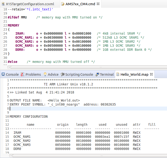
    Anyway, after installing the XDS Emulation Software Package, I discovered that it also contains GEL files for AM5728 so I've been trying to load my simple Hello World example onto M4 from CCSv7.  From looking at the memory map, it seems that the default configuration is to load the app to OCMC_RAM1 by default which I guess is what the 0x00300000 data validation error relates to.  So another thing I'm wondering is - does the .map file get generated from the cmd file?  What's the relationship between the two files?

    I hope those questions makes sense.

    Thanks,

    Dermot

  • Hi Dermot,

    When the DSP is loaded by Linux, RemoteProc parses the system resources defined in the resource table that is linked into the DSP image, and allocates the rpmsg vring buffers and trace buffer, and configure the DSP MMU. If the DSP image is loaded via CCS, this step will be skipped and you will probably run into issues.

    The default DSP resource table used for AM572x can be found at ./packages/ti/ipc/remoteproc/rsc_table_vayu_dsp.h.

    To debug the DSP after it's been loaded by Linux, you can connect to the core in CCS and load only the symbols. Running any GEL files would be destructive at this point since device initialization has already been done by Linux.

    The map file is generated by the linker and contains a summary of the memory configuration and section allocations defined by the linker cmd file. See: processors.wiki.ti.com/.../Files_in_CCS_Projects

    I hope this helps. If you have any other questions please let me know.
  • Hey Sahin,

    That makes a lot of sense.  Incidentally, regarding the use of GEL files, it wasn't until I discovered and installed the XDS Emulation Software package into ccs_base of Code Composer Studio that I had any GEL files available to me such as /ccsv7/ccs_base/emulation/boards/am572x/gel/AM572x_cortexM4_startup.gel.  I see some application examples have their own .gel files and I presume they should be used in preference to the more general ones when they're present.

    Thanks also for that CCS Files link - it's really useful,

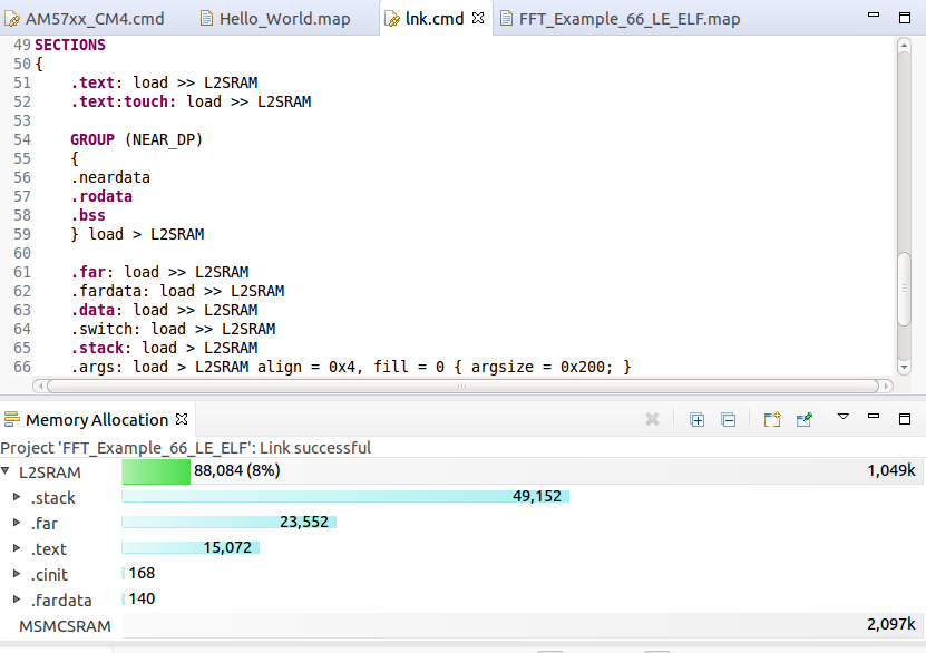
    One last thing - I had been assuming that a DSP or IPU image loaded by Linux will be placed into the CMA carveout as defined in the device tree - I'm starting to think that's a little over-simplistic now?  I guess the linker .map file is answering that particular question for me but it's actually making me a little more confused.

    Here's an extract from the .map file from one of the DSP examples I just built and it appears to be using GPMC space (0x00000000 to 0x1FFFFFFF) as opposed to DDR memory controller space (where the CMA carveouts would be) - although the L2SRAM name suggests otherwise:

    OUTPUT FILE NAME:   <FFT_Example_66_LE_ELF.out>

    ENTRY POINT SYMBOL: "_c_int00"  address: 00815460

    MEMORY CONFIGURATION

            name            origin    length      used     unused   attr    fill

    ----------------------  --------  ---------  --------  --------  ----  --------

     L2SRAM                00800000   00100000  00015814  000ea7ec  RW X

     MSMCSRAM              0c000000   00200000  00000000  00200000  RW X

    The value of 0x00800000 for the origin of L2SRAM is what's confusing me here since that appears to be in the range of GPMC space unless I'm interpreting those number wrong.

    Any light that you can shed on this would be a huge help!  In the meantime, I'll be reading through that CCS Files link in more detail.

    Thanks,

    Dermot

  • Hi Sahin,

    Well from looking at the linker command file associated with a simple "Hello World" project...


    #ifdef MMU     /* memory map with MMU turned on */

    MEMORY

    {

       IRAM:      o = 0x00000000 l = 0x00001000   /* 4kB internal SRAM */

       OCMC_RAM1: o = 0x00300000 l = 0x00080000   /* 512kB L3 OCMC SRAM1 */

       OCMC_RAM2: o = 0x00400000 l = 0x00100000   /* 1MB L3 OCMC SRAM2 */

       OCMC_RAM3: o = 0x00500000 l = 0x00100000   /* 1MB L3 OCMC SRAM3 */

       DDR0:      o = 0x80000000 l = 0x40000000   /* 1GB external DDR Bank 0 */

    }

    #else     /* memory map with MMU turned off */

    MEMORY

    {

       IRAM:      o = 0x00000000 l = 0x00001000   /* 4kB internal SRAM */

       OCMC_RAM1: o = 0x40300000 l = 0x00080000   /* 512kB L3 OCMC SRAM1 */

       OCMC_RAM2: o = 0x40400000 l = 0x00100000   /* 1MB L3 OCMC SRAM2 */

       OCMC_RAM3: o = 0x40500000 l = 0x00100000   /* 1MB L3 OCMC SRAM3 */

       DDR0:      o = 0x80000000 l = 0x40000000   /* 1GB external DDR Bank 0 */

    }

    #endif

    ...it looks as tough the mapping is a combination of virtual OCMC addresses (if MMU is turned ON) and physical DDR addresses.  That kind of makes more sense to me now.

    So, the 0x00800000 reference to L2SRAM in the DSP example's linker map file is most likely the virtual address of the DSP1 CMA at 0x40800000?  Am I on the right track?

    Thanks,

    Dermot

  • Actually, the Memory Allocation view is a very useful way to visualise the map too...

    So with my linker command file, I could decide to put all my code, stack, data, etc. in OCMC_RAM1 assuming it fits (as with the Hello World example app) or pretty much anywhere but ultimately it's up to me to ensure that there's no resource conflicts.

  • Hi Dermot,

    That's correct, you can use a linker.cmd or config.bld to define your DSP memory map. The resource table is then used to let Linux know about these definitions.

    These are the addresses only accessible by the DSP, also known as virtual addresses. You can see these defined in Table 2-10 DSP Memory Map of the TRM.

    Dermot Murphy said:

    MEMORY

    {

       IRAM:      o = 0x00000000 l = 0x00001000   /* 4kB internal SRAM */

       OCMC_RAM1: o = 0x00300000 l = 0x00080000   /* 512kB L3 OCMC SRAM1 */

       OCMC_RAM2: o = 0x00400000 l = 0x00100000   /* 1MB L3 OCMC SRAM2 */

       OCMC_RAM3: o = 0x00500000 l = 0x00100000   /* 1MB L3 OCMC SRAM3 */

       DDR0:      o = 0x80000000 l = 0x40000000   /* 1GB external DDR Bank 0 */

    }

    These are global addresses which are used by all bus masters, also known as physical addresses. These are defined in Table 2-1. L3_MAIN Memory Map. We generally recommend only using the global addresses in your application to avoid access issues.

    Dermot Murphy said:

    MEMORY

    {

       IRAM:      o = 0x00000000 l = 0x00001000   /* 4kB internal SRAM */

       OCMC_RAM1: o = 0x40300000 l = 0x00080000   /* 512kB L3 OCMC SRAM1 */

       OCMC_RAM2: o = 0x40400000 l = 0x00100000   /* 1MB L3 OCMC SRAM2 */

       OCMC_RAM3: o = 0x40500000 l = 0x00100000   /* 1MB L3 OCMC SRAM3 */

       DDR0:      o = 0x80000000 l = 0x40000000   /* 1GB external DDR Bank 0 */

    }

    This example by itself has nothing to do with CMA. To use CMA, you would need to use a resource table to let Linux know to allocate from the CMA pool defined in the dts file. 

    Hope this helps.

  • Thanks Sahin.

    Yeah - I don't know what I was smoking when was interpreting that 0 x00800000 address as CMA (it was getting late!).  It's clearly identified as L2 SRAM in the DSP memory map.

    I do appreciate your help & patience with my many newbie questions.

    Dermot

  • No problem! Please mark this thread as resolved so I can close it. If you have any more questions feel free to click the "Ask a related question" button. Thanks.
  • Will do. Incidentally, I've been working through the steps in the "Adding IPC" document at the link below:
    processors.wiki.ti.com/.../Linux_IPC_on_AM57xx

    I'd be happy to send on a summary of the bits that were a little unclear to me if that would help with the next rev. of the document.