Part Number: PROCESSOR-SDK-TDAX
Other Parts Discussed in Thread: AWR1243
Tool/software: TI-RTOS
Dear community members,
I am developing an awr1243 cascade system with custom antenna topology, and its control and data logging is implemented by TDA2x processor (and FPGAs).
The configuration of the system is successfully done using "PROCESSOR-SDK-RADAR",
and I checked all the range profiles are working without any problem with using 12Tx (and TDM-MIMO).
however, the calibration between the virtual antennas seems not working due to modified antenna positions.
I am evaluating the system performance by using usecase "Object detection",
so I tried added and modify the antenna topology which is described in "chains_cascadeRadarOd.c" in Processor SDK example.
(because this usecase example only uses 8 Tx, and I want to use all of them by TDM-MIMO)
In shortly, my question is that how I can allocate each antenna position in the source code, and how is it possible to distinguish the 4 ar12xx chips.
(I only know what is the master chip and can't distinguish between slave chips)
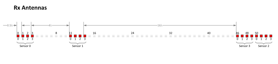
I think I am having problem in especially in "gAoa_sensorRxOffset", How I can fill out this structure in what order?
Thank you.
Best regards,