This thread has been locked.

If you have a related question, please click the "Ask a related question" button in the top right corner. The newly created question will be automatically linked to this question.

RTOS/AM6548: A question about default pinmux configuration

Part Number: AM6548

Tool/software: TI-RTOS

Hi, TI engineers

Thanks for the help all the times, I want to ask a question the default configuration of pinmux.

at the file:am65xx_evm_pinmux_data.c,

it just set up  AD9&AC8(USBX_DRVVBUS) just as the source below

static pinmuxPerCfg_t gUsb0PinCfg[] =
{
    /* USB0 -> USB0_DRVVBUS -> AD9 */
    {
        PIN_USB0_DRVVBUS, PIN_MODE(0) | \
        ((PIN_PULL_DISABLE) & (~PIN_PULL_DIRECTION & ~PIN_INPUT_ENABLE))
    },
    {PINMUX_END}
};
static pinmuxPerCfg_t gUsb1PinCfg[] =
{
    /* USB1 -> USB1_DRVVBUS -> AC8 */
    {
        PIN_USB1_DRVVBUS, PIN_MODE(0) | \
        ((PIN_PULL_DISABLE) & (~PIN_PULL_DIRECTION & ~PIN_INPUT_ENABLE))
    },
    {PINMUX_END}
};

why it doesn't need to set up other pins of USB?
such as“USB0_DM/AE2  USB0_DP/AF1  USB0_VBUS/AE7”
I think the reason about it is that AD9&AC8 has two muxmodes:USB0_DRVVBUS and GPIO1_71,
while the others(AE2 AF1 AE7) just has one muxmode.
so we should set up AD9&AC8 especially。
is my thought right?

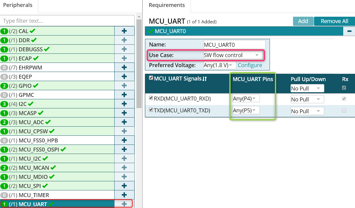
then I looked up the pin config of UART, it just configed MAINUART0 MAINUART1 WAKEUPUART and didn't config MCUUART.
but I can output to MCUUART as well, the pin MCUUART used(P1 P4 P5 N3)also have several muxmodes,
why they don't need to me config especially?

Best Regards

  • Hope_Chen,

    The pinmux code in the board library is auto generated code from the TI pinmux tool so looking at the variable names is not the best way to determine what USB pins have been used in the board library. The pin names in the design some times use the name of the peripheral which is the default mode setting of that pin. For example AC8 is referred to as PIN_USB1_DRVBUS as per datasheet but can also be a GPIO pin:

    Then there are some pins that have only one mux mode which is the default mode of the pin so no pinmux is required. For example in the board library  AD2 and AE1 (DP, DM) are enabled 

    The correct approach to check what pins are enabled for a peripheral interface is to import the bae line pinmux project file for the platform in the TI pinmux tool.

    1. TI pinmux tool : 

    http://www.ti.com/tool/PINMUXTOOL 

    2.  GP EVM and IDK pinmux project files:

    http://www.ti.com/tool/TMDX654GPEVM#technicaldocuments (Design files)

    Note: It appears that the link from ti.com is broken so I am sharing the files here:

    board_files.zip

    You can install offline installer or use the cloud version of the tool.  When you open the tool, go to Open->Local Drive and browse to am6548_gp.pinmux or am6548_idk.pinmux file based on the platform that you are using. 

    When you open the tool and import the .pinmux project  in the tool you should see a view as shown here:

    As you can see for USB0 , pins AE2, AF1, AD9, AF7 and AE7 are enabled. The files AM65xx_pinmux_data.c and AM654x_pinmux.h are then used in the PDK package to apply the pin settings. 

    Same concept applies to MCU_UART as well . The pin P4 and P5 are selected in the pinmux tool but we don`t use HW flow control so N3 and P1 are not selected.

    Hope this helps clarify how the pins have been set up. Let us know if you still have questions.

  • Hi Rahul

    I really appreciate your detailed explanation,

    I still have something that I didn't understand well.

    in brief,  I cannot find where the USB1_DM(AD2) enabled in the file "AM65xx_pinmux_data.c"

    and your means that in this file,  AD2's name is PIN_GPMC0_AD2,

    then I searched where PIN_GPMC0_AD2 is setup(as below),

       /* VOUT1 -> VOUT1_DATA2 -> M28 */

       {

           PIN_GPMC0_AD2, PIN_MODE(1) | \

           ((PIN_PULL_DISABLE) & (~PIN_PULL_DIRECTION & ~PIN_INPUT_ENABLE))

       },


    the value of PIN_GPMC0_AD2 in AM65xx_pinmux.h is 0x0008(so offset is 0x0011C008 )

    then I look up it in the datasheet (as below),


    But it seems that PIN_GPMC0_AD2 is PIN_NUM M28,not AD2,

    so I still how the USB1_DM(AD2) been enabled,

    would you please help me with it?


  • Hi Rahul

    Maybe I have known the question i asked.
    if a pin just have only muxmode, it doesn't need to be setup especially.

    Best Regards
    Hope Chen
  • Hope_Chen,

    Thanks for your kind words.  I updated my response with some screenshots from the data sheet to fix some signal  names and examples that I provided. In general looking at the datasheet I realized AD2 and GPMC_AD2 are not the same pin/signals so fixed my previous response.

    In general, your observation is correct. If you look at the datasheet AD2 (USB1_DM) has only one functionality and this is the default reset functionality of the pin so Pinmux tool doesn`t generate output for that pin so you may not find reference for it in the pinmux_data.c file

    Once you select the peripheral and the usecase, the output generated should have all required pins enabled which you can also confirm by reading back the corresponding PADCONFIG register. for example data manual indicate PADCONFIG176 corresponds to AC8 pin that sets USB1_DRVBUS. And looking at the TRM, last 4 bits of the CTRLMMR_PADCONFIG176 can be checked to see that the correct setting is done.

    Regards,

    Rahul 

  • Hi Rahul

    Yeah,I know, your answer is very helpful for me .

    Yet I want to ask one more question,

    In the pinmux tool, I take a example with GPIO1_13(as below),

    I changed the pin from Any(A23) to A23,

    then a lock icon comes out, with a tips “Current user selection cannot be changed by the solver when resolving other requirements”,

    I could not understand it well,

    I want to know the difference between Any(A23) & A23,

    and in addition, would you please make an explanation about “Current user selection cannot be changed by the solver when resolving other requirements” for me?

    Best Regards

    Hope Chen