Other Parts Discussed in Thread: TMDSEVM572X, SYSCONFIG
I enabled SPI 3 IOSet 2 in a pinmux file, created a custom board and rebuilt the pdk. I was able to generate SPI examples and use the custom board to run the examples. The two examples I ran were the "MCSPI_BasicExample_idkAM572x_c66xExampleProject" and "MCSSPI_Loopback_idkAM572x_c66xExampleProject". The only thing I modified was the board to point to my custom board.
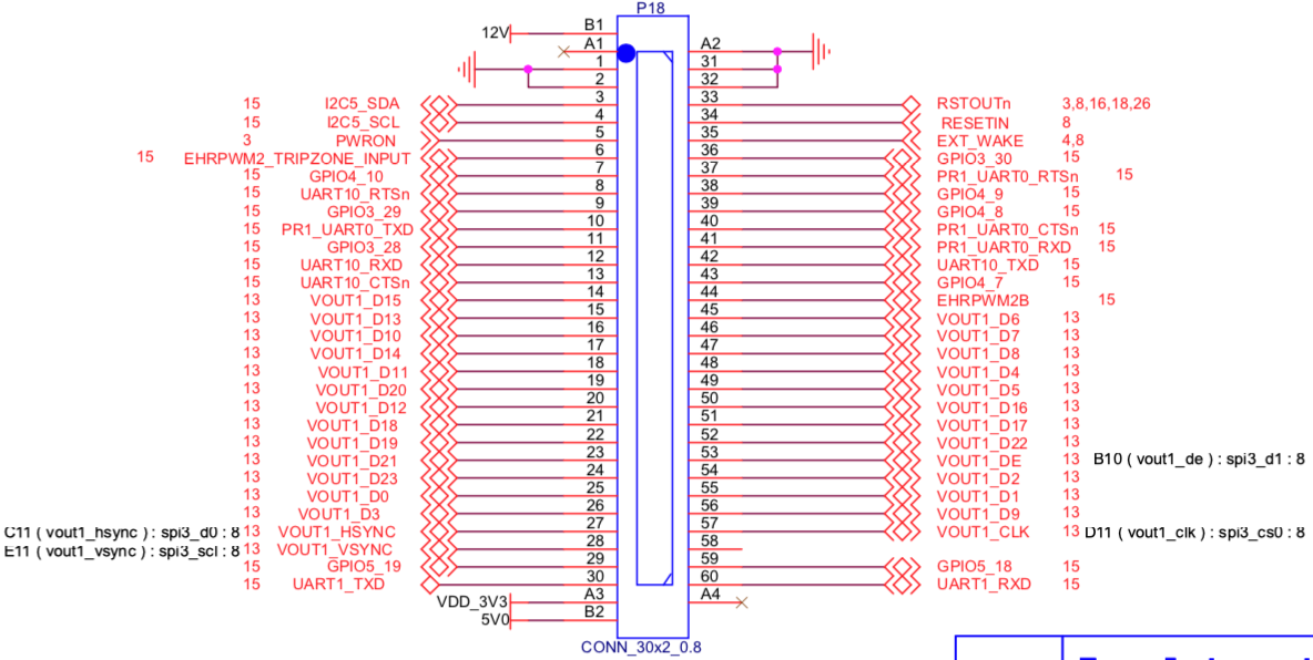
I monitored the following exposed pins on P18:
- spi3_sclk : E11
- spi3_d1 : B10
- spi3_d0 : C11
- spi3_cs0 : D11
These examples didn't seem to modify the outputs on the exposed pins. I didn't see the clock signal or see the CS0 oscillating when running the code.
I would like to generate the "SPI_TestApplication" to see if it outputs to the exposed pins, but this project doesn't get generated when I run.
./pdkProjectCreate.sh AM572x all little spi all dsp
Two questions:
- How can I generate the SPI_TestApplication example for the AM5728 SoM?
- Should I see the pins output correctly for the two example projects that I ran, or do they not output to the pins?