This thread has been locked.

If you have a related question, please click the "Ask a related question" button in the top right corner. The newly created question will be automatically linked to this question.

TDA2E: EVE output data format with beamforming in Processor Radar SDK

Part Number: TDA2E
Other Parts Discussed in Thread: TDA2, AWR1243

Hi expert,

We are working on TDA2+AWR1243 cascade board for beamforming test. There is two TX beam steering which is chirp based and frame based as below


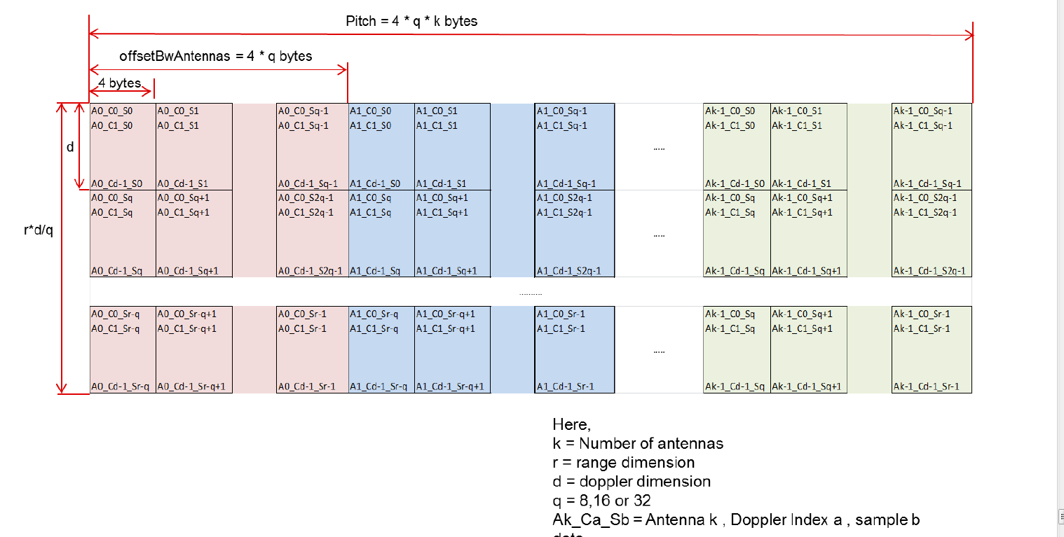
Is the EVE output data format same in these two scenarios? As mentioned in the graph as below. If not, what's the difference?

Thanks a lot. 

Best Regards, 

Allen

  • Hi Allen,

       The figure which you mentioned is the output of Doppler FFT from the EVE processing. This will be same irrespective of the input, what will actually change is the way input is given to EVE FFT applet. The input is described using FFT_TI_BufferDescriptor structure. We have validated he first case (Chirp based). But I can see a potential problem if you use frame based sequence as TDA2X dma supports a maximum jump of 16 bit signed integer so if your frame jump is more than maximum 16 bit signed integer it will not work. 


    Regards,

    Anshu

  • Hi Anshu,

    Based on the sequence of frames, the number of frames is equal to the number of burst. In radarFft2. C, Eve is operated in the unit of burst. The input and output addresses correspond to their respective offset and width. How can I get the DMA parameters corresponding to the input and output of Doppler FFT.

    My Doppler FFT  results are incorrect.

    Thanks.

  • Hi Allen,

       DMA is programmed inside FFT_TI_dmaControl ( file : apps\fft\algo\src\fft_graph_int.c ). For doppler FFT fftDirection value will be FFT_TI_DIRECTION_VERTICAL. 


    Regards,

    Anshu