This thread has been locked.

If you have a related question, please click the "Ask a related question" button in the top right corner. The newly created question will be automatically linked to this question.

66AK2H14: PRBS testing

Part Number: 66AK2H14

Hi,

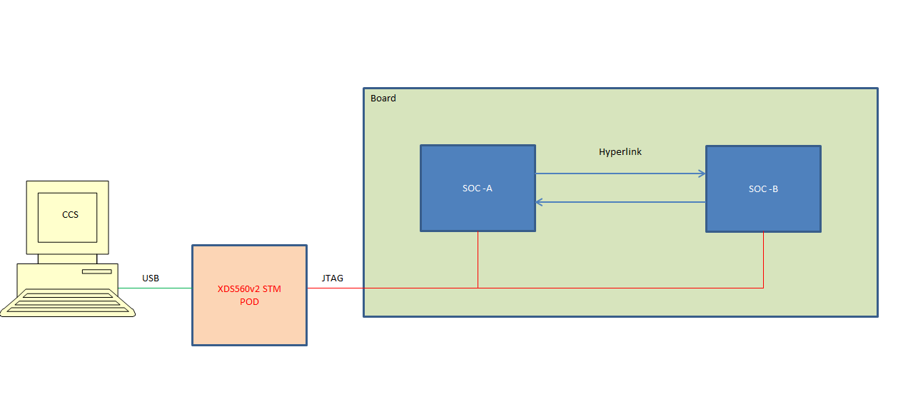
I am currently aiming for SRIO PRBS testing in a configuration where the 66AK2H14 will receive PRBS23 pattern from external driver.

I read the "serdes_diag_user_guide " (June 2017)  document and prepared the required modification :

I first set SERDES_DIAG_TEST_LOOPBACK_MODE to CSL_SERDES_LOOPBACK_DISABLED (serdes_diag_platform.h file)

1) My question is about the 2nd modification:

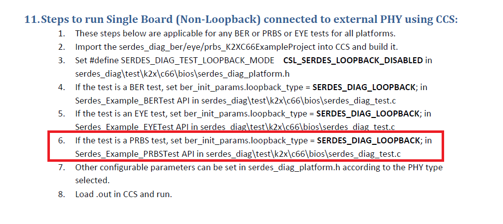
The way item 6 is written seems to me not that clear.

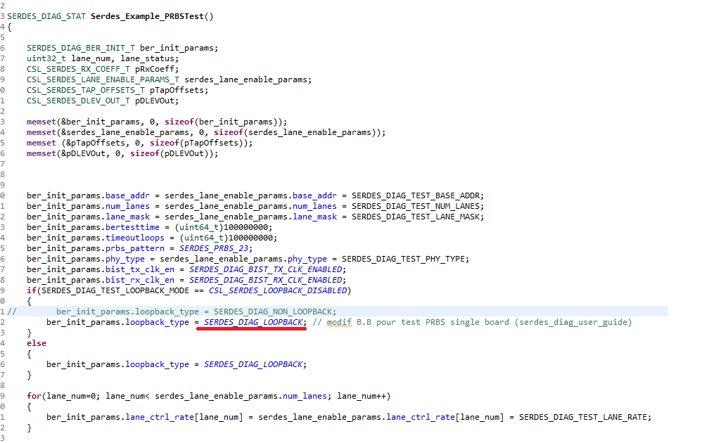
Inside the "serdes_diag_test.c"  file I only found the "ber_init_params.loopback_type" once, and it is inside an "if" operation.

I did the following modification (see red underline)and want to know if this is what is expected from the user_guide :

(This forces "ber_init_params.loopback_type" to SERDES_DIAG_LOOPBACK whatever the SERDES_DIAG_TEST_LOOPBACK_MODE is)

2) another subsidiary question is to know to force TX side of the 66ak2h14 to also generate pure PRBS23 pattern. (even if no loopback exists outside)

with best regards,

Bruno

  • Hi,

    From the user guide, you need two changes for this:

    1. Set #define SERDES_DIAG_TEST_LOOPBACK_MODE CSL_SERDES_LOOPBACK_DISABLED in serdes_diag\test\k2x\c66\bios\serdes_diag_platform.h========> did you do this?

    2. If the test is a PRBS test, set ber_init_params.loopback_type = SERDES_DIAG_LOOPBACK; in Serdes_Example_PRBSTest API in serdes_diag\test\k2x\c66\bios\serdes_diag_test.c ==========>I saw you did this

    For how to generate PRBS23 pattern, 

        ber_init_params.prbs_pattern = SERDES_PRBS_23; ======> you already did this in the Serdes_Example_PRBSTest().

    Regards, Eric

  • Hi Eric,

    Thank you for your quick reply.

    1) I was first wondering if everything was correct at the software level because my external receiver do synchronizes at 5G upon the incoming bitstream, but does not detect any PRBS23 pattern. And since there are a lot of options in the BIST generation , may be I was forgetting something....we don't want any preamble, nor K28xx, nor anything else but the pure PRBS pattern.

    2) By the way can you explain the meaning of "LOOPBACK" used inside the word "CSL_SERDES_LOOPBACK...DIS/EN..ABLED". Are we speaking of external loopback (Serdes TX pins being looped backed into serdes Rx pins by external hardware) ? or internal loopback where the serdes TX does not go out of the 66ak2h14 component ?

    3) This is also quite confusing when reading the user_guide .For example §11 Title : "Steps to run Single Board (Non-Loopback) connected to external PHY using CCS", or §10 Title : "Steps to run Single Board (Loopback) using CCS". Is this relating to loopback external to the SOC , or internal ?

    4) What is the purpose of LB_NES loopback ?

    regards,

    Bruno

  • Hi Eric,

    Don't worry anymore about my PRBS problems. I discovered that the P/N lane polarities were swapped before reaching the external receiver. The setup is working correctly now.

    Nevertheless I am still interested in your answers for questions 2) and 3) and 4)

    with best regards,

    Bruno

  • Bruno,

    Glad to know the PRBS pattern issue was resolved. The Serdes test code is mainly developed for board to board test (non-loopback), it also supports the single board loopback and Single Board (Non-Loopback) connected to external PHY, I haven't used it. 

    When looked at the code, in the case of 

    1. single board loopback

    • Set #define SERDES_DIAG_TEST_LOOPBACK_MODE CSL_SERDES_LOOPBACK_ENABLED
    • ber_init_params.loopback_type = SERDES_DIAG_LOOPBACK

    This should be the internal loopback and Serdes signal doesn't come out of the chip

    2. Single Board (Non-Loopback) connected to external PHY 

    • Set #define SERDES_DIAG_TEST_LOOPBACK_MODE CSL_SERDES_LOOPBACK_DISABLED, then the 
    • ber_init_params.loopback_type = SERDES_DIAG_NON_LOOPBACK =====> need to change to SERDES_DIAG_LOOPBACK

    This should be the external loopback and Serdes signal doesn't come out of the chip and rely on an external device to loop it back (PHY)

    The LB_NES is explained in the serdes user guide section 19.2, the code set the lane 0x200 register bit 30 (NES_LB_ENA_O) =1 from CSL function CSL_SerdesSetLoopback().

    Regards, Eric

  • Thank You Eric,

    May I ask another question, still about diag_test..?

    The "Serdes Diag User Guide" document describes BER procedure based upon 2 distinct emulators platform.

    Is it possible to run the same HYPERLINK BER test on a single board where both 66ak2h14 are managed by an unique XDS5660v2 STM emulator ? and how ?

    Thank you for supporting me,

    with best regards,

    Bruno

  • Hi Bruno,

    For Hyperlink on K2H, it typically runs at 3.125, 5.0, 6.25, 7.5 or 10.0 Gb/s x 4 lanes (or 1 lane). For lower baud rate (3.125, 5.0), you don't have to run the BER test and the typical Serdes setting (Tx side: C1, C2, CM, Rx side: ATT and BOOST) are robust. For higher baud rate (>= 6.25), it is suggested to run BER to tune up the settings as the each board design and connection are different.

    The TI utility is mainly designed for board to board test with the same TI SOC. I haven't done any one board test, it has to be in some loopback fashion. You can try what you did with the SRIO case for the Hyperlink, Single Board (Non-Loopback) connected to external PHY. Hyperlink is a TI protocol, you need a device to understand it (maybe some FPGA supporting TI Hyperlink) if you want to check the pattern. Or you may loop at the Hyperlink TX and RX pins.

    There is also single board loopback where signal didn't go out of the chip you can try. But I think eventually you need board to board test when you connect K2H to another devices with high speed. 

    There is a Serdes tuning application note you can refer to 

    Regards, Eric

  • Hi Eric,

    When looking at my previous picture you can see that the 2 hyperlink partners are both 66ak2H14 located on the same board. There is no question of FPGA, nor other electronics.

    Both 66ak2h14 are controlled by the same emulator.

    The targeted datarate being 10Gb/s we would like to execute some BER tests. First test with SOC-A driving and SOC-B analyzing. Second test with SOC-B driving and SOC-A analyzing.

    To do so the hyperlink driver and hyperlink receiver must be synchronized in some way because the Rx side must be informed when the Tx side changes its CM,C1,C2 driving parameters, and when restart the new error counting sequence.

    I guess that this is performed by DSS in a board-1/board-2 setup when 2 different emulation pods are used, (one being connected to board-1 SOC, the other being connected to board-2 SOC) . Probably DSS sends start and resume commands to each emulator .....

    Therefore my question is to know if there is a way to configure DSS (I don't know exactly what DSS is)  , so that to mimic the same synchronization behaviour but with a single emulator pod controlling the 2 partners in my ONE board setup.

    Is this possible ?

    Regards,

    Bruno

  • Hi Bruno,

    I noticed this is not closed yet. Sorry, it is taking time to address your issue.

    Let me contact the local expert on this to provide suggestions to you.

    By the way, is this still an outstanding issue for you? OR it is resolved? Please let me know.

    Thanks,

    Aravind

  • Hi Bruno,

    DSS can be used to run the BER test between the 2 SOCs connected to the same emulator. You can create a dual 66AK2H14 under the same emulator as below:

    Once you do that, you can modify the DSS script so that the names of the cores will point Device 1 to 66AK2H14_0 and Device 1 to 66AK2H14_1. Everything else should work as it is. 

    Regards,

    Arun

  • Hi Aravind and Arun

    Thank you for your help.

    I updated the ccxml target-configuration file , as well as the .JS so that to call the new session name

    But since I understand there are some "writing specificity" depending upon the CCS version, I am not sure this is correct for my use case (CCSv910).

    Furthurmore launching the DSS script does not work as expected

    IT seems that dialog with the POD fails although the "Test Connection" performed under CCS environment is OK :

    By the way I have some other POST still waiting for some answer....(from November the 10th, and November the 13)

    With best regards,

    Bruno

  • Hi Bruno,

    Yes, the naming convention keeps getting updated in the newer releases. So the best way to figure out the exact name is to launch the target configuration via CCS and copy the core names from CCS into the DSS script. 

    If test connection worked for the dual EVM target, thats a good sign. When you launch the .js file, are you making sure that CCS is closed? Because if the target configuration is open in CCS, DSS won't be able to access the DAP. 

    Regards,

    Arun

  • Hi Arun

    I took the following information from CCS and updated the DSS script with the corresponding naming

    I also closed CCS before launching the DSS script....and removed any remaining sd560v2u_server from the windows task manager.

    but unfortunately the results is the same

    Isn't it strange to get the "download failed for file .... xds560v2.out" message ? I have verified that the file do exist.

    Regards,

    Bruno

  • Hi Bruno,

    The links to all your screenshots are broken. Can you repost them? If you continue to have issues, please see the below faq:

    https://e2e.ti.com/support/tools/ccs/f/81/t/821597

    Thanks

    ki

  • Oops, sorry !

    CCS environment

    DSS session name update

    result :exactly same as before

  • Thanks.

    The error you are getting is known as a host connection error. Basically the debugger is unable to communicate with the debug probe (your 560v2 in this case). The root case can vary greatly. Because the Test Connection command passes in CCS, the probe appears properly powered, configured, and detected by the host OS. My guess is that CCS still has a connection to the debug probe, even though you shut down CCS.

    You can try using the DTC CONF utility to see if the probe is being accessed by another program:

    https://software-dl.ti.com/ccs/esd/documents/xdsdebugprobes/emu_dtc_conf.html

    If all else fails, try rebooting your PC. I have had to resort to this occasionally when I could not resolve the issue otherwise.

    Hope this helps

    ki


  • Hi Bruno,

    Can you please let me know if this is resolved at your side? If yes, please mark it as "resolved".

    Thanks,

    Aravind

  • Hi Aravind,

    Unfortunately I was not able to solve the problem.

    I am currently waiting for some software colleagues to help me.

    Bruno

  • Hi Aravind,

    We finally solved our problem :

    In the JS file we changed the line

    var session0 = server.openSession(sessionName0);

    into

    var session0 = server.openSession("*","C66xx_0");

    It is OK now.

    With best regards,

    Bruno

  • Hi Bruno,

    Glad to hear that your issue is resolved. Thanks for letting us know about it and clicking "resolved" on this thread.