This thread has been locked.

If you have a related question, please click the "Ask a related question" button in the top right corner. The newly created question will be automatically linked to this question.

Putting data on the Vertical Blanking Interval limatation and the other reolved method consultation

Dear Folks and TI specialist:

A.

I encounter the problem about putting data to Vertical Blanking Interval(VBI). I try to put data on the VBI but I found sometime the extracted frame size(log is from 8148) are not correct.

Ex: video format is 720p59.94. the extracted frame size should be always video frame size: 1280x720 and VBI frame size:1280x30. But I found the frame size is sometime video frame size: 1280x720 and VBI frame size: 1280x15. The VBI frame size is always not correct.

(P.S The 8148 VIP port setting is “16 bit 4:2:2 YCbCr embedded sync mode”.)


[m3vpss ]      |   Total    Even     Odd  Total  Even   Odd  Min /  Max  Min /  Max Dropped Fid Repeat Frame Error Y/C

 [m3vpss ]  CH  |  Fields  Fields  Fields    FPS   FPS   FPS       Width      Height  Fields      Count (Desc Error Y/C)

 [m3vpss ]  ------------------------------------------------------------------------------------------------------------

 [m3vpss ]  000 |     682     682       0     62    62     0 1280 / 1280  720 /  720       1          0 0/0 (0/0)

 [m3vpss ]  010 |     683     683       0     62    62     0 65535 /    1   15 /   15       1          0 0/0 (0/0)


I think the reason is

  1. putted data sequence should not be FF, 00, 00
  2. Based on my test, the latest byte before EAV pattern should not be 00(h) or FF(h).


I want to know if anyone have the experience about this and can help me confirm if my reason is right about putting data on the VBI limitation .


B.

We have been considered to use 16 bit 4:2:2 YCbCr discrete sync mode but I have one consideration. I think the 16 bit YCbCr discrete sync mode implementation need to be taken more time because I need to support all video format and sync timing are all not the same. (I mean FPGA need support H_sync/V_SYNC/de/Field timing for all video formats and the timing need to follow CEA861.)

But after study HDVPSS user guide, seem the implementation is not very hard because 8148 VIP module receipt rule is easier for me.


Seem I only need to parse XYZ word in the SAV/EAV pattern and based on the parsed result (get F, V, H value) to assign H_sync/V_SYNC/de/Field value.(and delay video stream with parsing period).


The same as A. 

I want to know if anyone have the experience about this and can give me some suggestion.


C.

In addition of (A and B), I also want to hope anyone can provide the other ideas for resolving the problem.

Thank you!!!


Environment:

DM8148 is my device and use VIP0 to receive video data(BT1120 or BT656). The VIP source device is FPGA. The connection is YcbCr 12bit 4:2:2 embedded sync mode.


  • Hi,


    Please find answers to your questions,

    1, VIP port does not know/care about input stardard, it captures frame data and vbi information based on the sync codes i.e. SAV and EAV codes, if these codes are not correct, then it is possible that you get incorrect size for the VBI data. Please note that VBI data is captured only from one of the input channel i.e. either luma or chroma input channel. There is configuration which tells vip to use either luma or chroma channel for sync code detection. it uses same channel for capturing vbi data. Please use correct channel here. Also Please note that there should not sync codes or its preemble as part of you data otherwise vip could falsely detect it as sync code and you could get wrong output.

    2, Well, you could also have separare sync with the 16bit input, but you cannot capture hbi data, only vbi data can be captured. You could make your DE line high during active period and make vsync line high during vblank period, and configure VIP in discrete sync capture mode with correct sync polarity and discrete non-basic mode, this will capture active video and vbi data in separare buffers.


    Regards,

    Brijesh

  • Dear Brijesh:

    Thank you for your reply.

    We don't have experience with DM8148 8/16bit discrete sync mode so i real need more detail information about it.

    My question is as the following.

    A.

    You mention that “Also Please note that there should not sync codes or its preemble as part of you data”. What is “preemble as part of you data”. Is your mean that “FF 00 00” sequence appear on my VBI data?

    B.

    Do the data content (on the VBI) have any limitation when use 16/8 bit discrete sync mode? Can the data content be sync word?

    C.

    The others consideration point.

    I also plan to support 8bit YCbCr discrete sync mode so my question is whether we can get the total VBI data with 8bit 4:2:2 YCbCr discrete sync mode. Dose have any difference with 16bit mode?


    D.

    After study HDVPSS user guide, I think the got VBI zone is not the same between 16bit 4:2:2 YCbCr discrete and embedded sync mode. (video format is interlace.)

    Example:

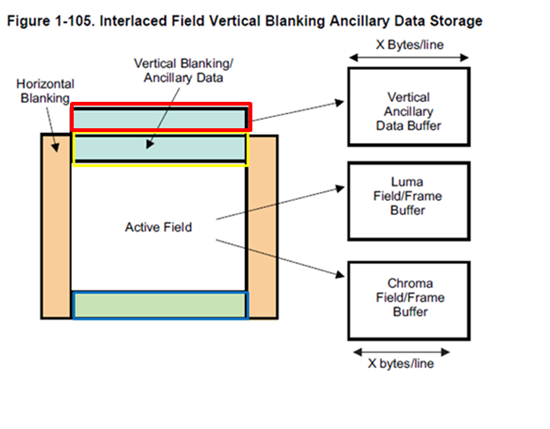
    Please refer to the picture. For active field in the picture


    16bit 4:2:2 YCbCr embedded sync mode

    =>The got VBI block data should be red outline border block + yellow outline border block.


    16bit 4:2:2 YCbCr discrete sync mode

    =>The got VBI block data should be yellow outline border block + blue outline border block.


    Does my idea is right? The start line for the VBI is not the same. It is depend on field ID for discrete sync mode.

    And

    whether the blue outline border block data will follow yellow outline border block data in the data buffer?(using 16bit 4:2:2 YCbCr discrete sync mode and video format is interlace.)


  • Hi Huang,


    Pl;ease find below answers to your questions

    A, Yes, by preemble, i meant FF 00 00 sequence,

    B, No limitation in discrete sync mode

    C, For 8bit discrete sync input, you will get complete VBI data, whereas for 16bit discrete sync input, as far as i know, you will get vbi data from only for one of the channel.

    D, all this depends on when vsync in discrete sync mode and vbit in embedded sync mode toggles. If you toggle both of then at the same time, you will get the same data in both the cases.


    Regards,

    Brijesh

  • Dear Brijesh:

    About C point (8bit discrete sync input), I know the video data sequence is CbYCrY… and 8148 wil separate Y, Cb and CR to the difference buffer so I want to know whether the VBI data will be separated to the difference buffer as well.

    Ex:

    VBI data sequence are A1B1A2B2A3B3 …

    Will the data be separated into two group when 8148 receive those data? A group include A1A2A3… B group include B1B2B3…

    Or

    Are the total VBI data sent to the same buffer? The sequence is also A1B1A2B2A3B3 …


    About D point

    D.1.

    I want to confirm whether the behavior(depend on vsyn signal/bit to change data-in buffer) is the same as 8 bit discrete sync mode.

    D.2

    Will we always receive the same VBI data If v bit and vsync timing are the same? Is it right no matter using 16 bit embedded/discrete sync mode or 8 bit embedded/discrete sync mode?

    I mean that I don’t hope software side need any modification after FPGA change from embedded mode to discrete mode.


    Thank you again for your reply.

  • Hi Huang,


    For C,

    You will get the total VBI data in the same buffer, so the buffer will have A1B1A2B2A3B3, There are no two channels for the VBI data as for luma and chroma data.


    For D.1

    there is no other way for the VIP to detect vbi period, it has to rely on the vbit in embedded sync format and start of vsync signal in discrete sync format. So it does not matter whether it is 8bit or 16bit, the behaviour remains same, only difference as i said, in discrete sync, it will capture vbi only from one of the channel where embedded sync are present.

    For D.2

    Same as D.1, there is no otherway for the VIP to know start of vbi period.


    Regards,

    Brijesh

  • Dear Brijesh:

    About D.1

    You mention " only difference as i said, in discrete sync, it will capture vbi only from one of the channel where embedded sync are present."

    If using 16bit discrete sync mode and two channel have embedded sync signal, I want to know which channel VBI will be captured? Is't the captured channel select setting by the software seeting? 

    Regards,

    Troy Huang

  • Hi Huang,


    Yes, it is configurable, it will capture the VBI data from the channel you have configured to detect the sync codes. So lets say, if you configure VIP to detect sync codes from luma channel, then it will capture vbi only from luma channel. There is an interface in the VIP driver configure this.


    Regards,

    Brijesh

  • Dear Brijesh:

    Very thanks for your technical support but i still have a little bit confusion. Please help me clarity it.

    I want to confirm with you again. Now we are discussing discrete sync mode so the extracted data(also include VBI data) timing is depended on discrete sync signa (not embedded sync signal)l but the extracted channel is depended on VIP driver configuration(luma or Chroma).

    Regards,

    Troy Huang

  • Hi Huang,


    That's corrent, but please note that this is not tested, so may require some change.


    Regards,

    Brijesh

  • Dear Brijesh:

    About D point, I want to confirm again. If the video format is interlace mode, how to judge field 1 OR 2? Do you have any real case? Can you share the picture to me for implement interlace discrete sync mode? I need the timing chart to follow it especial I am not sure field_ID signal timing.


    Best Regards,

    Troy

  • Hi Huang,


    Please refer to the BT1120 specs, it clearly shows when FID bit or fid signal should toggle for the field id change.

    There are also other ways of detecting field id, but you could provide fid signal, that's the best.


    Regards,

    Brijesh